
Fuel cell system and performance improvement method of fuel cell system

a fuel cell and performance improvement technology, applied in the direction of fuel cells, electrochemical generators, electrical equipment, etc., can solve the problems of deterioration in the performance of the single fuel cell may not be sufficiently improved, so as to achieve the effect of improving the durability of the electrode catalyst, reducing the performance of the single fuel cell, and improving the performance of the electrode catalys

Active Publication Date: 2019-02-05
TOYOTA JIDOSHA KK
View PDF9 Cites 2 Cited by
  • Summary
  • Abstract
  • Description
  • Claims
  • Application Information

AI Technical Summary

Benefits of technology

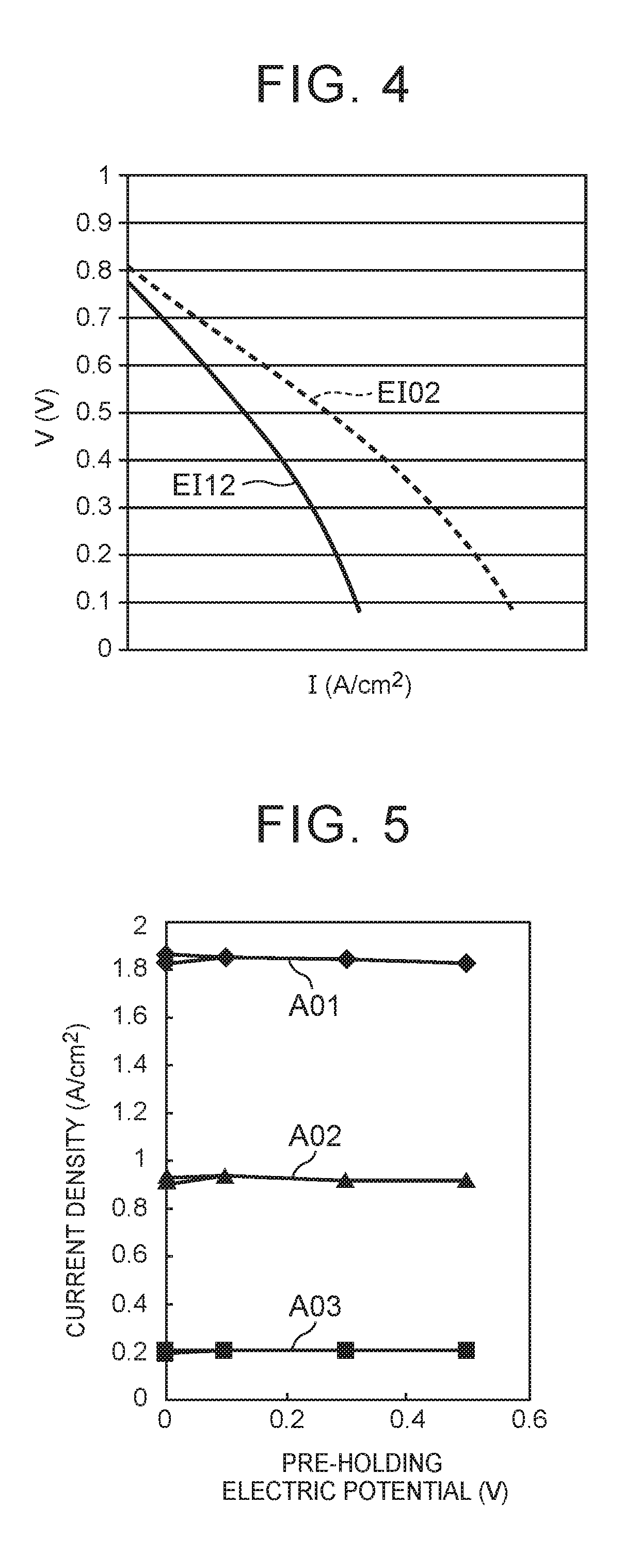
[0007]The present inventors performed an investigation on the activation process and found that, even in a case where the activation process is performed on a single fuel cell at a predetermined cathode electric potential, the performance of the single fuel cell may not be sufficiently improved. By performing the activation process on a single fuel cell at a lower cathode electric potential than the predetermined cathode electric potential, that is, to a higher degree of the activation process, the performance of an electrode catalyst can be improved regardless of the state of the single fuel cell. However, in a case where the activation process is performed to a higher degree of the activation process, an excessive activation process promotes dissolution of metal in an electrode catalyst, which may cause deterioration in the durability of the electrode catalyst. A technique capable of performing the activation process to an appropriate degree and reliably improving the performance of a single fuel cell is required.
[0011]In the fuel cell systems according to the above-described aspects, the activation process can be performed to an appropriate degree, and the performance of a single fuel cell can be reliably improved.

Problems solved by technology

When an electrode catalyst of a cathode of a single fuel cell is used, an oxide film is formed on a surface of the electrode catalyst, which causes deterioration in performance of the electrode catalyst.
The present inventors performed an investigation on the activation process and found that, even in a case where the activation process is performed on a single fuel cell at a predetermined cathode electric potential, the performance of the single fuel cell may not be sufficiently improved.
However, in a case where the activation process is performed to a higher degree of the activation process, an excessive activation process promotes dissolution of metal in an electrode catalyst, which may cause deterioration in the durability of the electrode catalyst.

Method used


Image

  • Fuel cell system and performance improvement method of fuel cell system
  • Fuel cell system and performance improvement method of fuel cell system
  • Fuel cell system and performance improvement method of fuel cell system

Examples


Embodiment Construction

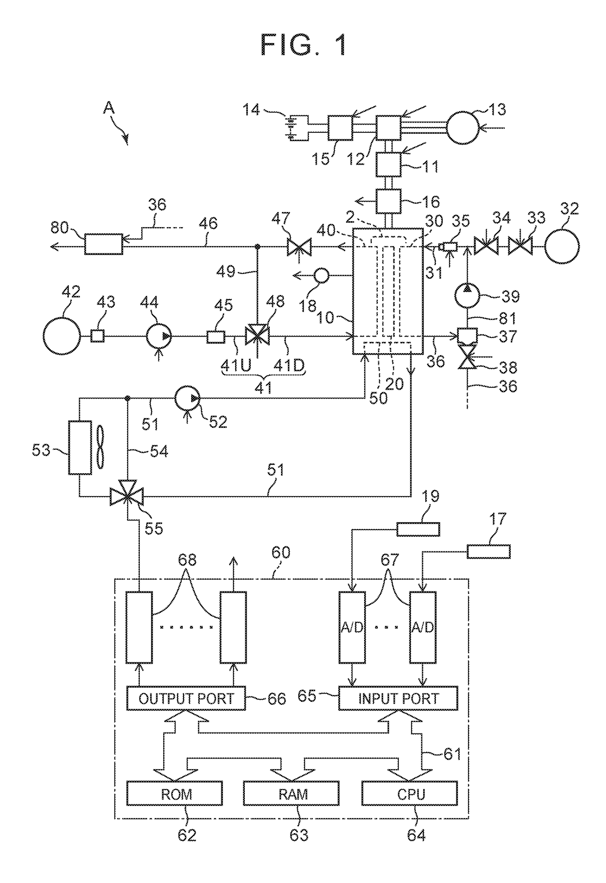
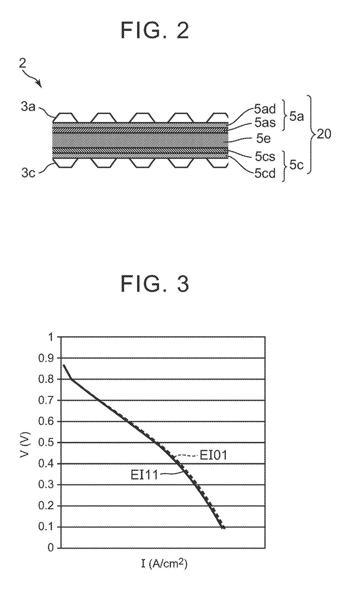
[0045]Referring to FIG. 1, a fuel cell system A includes a fuel cell stack 10. The fuel cell stack 10 includes a laminate including plural single fuel cells 2 that are laminated in a laminating direction. Each of the single fuel cells 2 of the laminate includes: a membrane-electrode-gas diffusion layer assembly 20; and separators (not shown) that are disposed on opposite sides of the membrane-electrode-gas diffusion layer assembly 20. The membrane-electrode-gas diffusion layer assembly 20 includes: an electrolyte membrane; and an anode and a cathode that are disposed on opposite sides of the electrolyte membrane.

[0046]An anode of one single fuel cell 2 is electrically connected to a cathode of another single fuel cell 2 adjacent to the single fuel cell 2 on a first side of the laminate through a separator, and a cathode of the single fuel cell 2 is electrically connected to an anode of another single fuel cell 2 adjacent to the single fuel cell 2 on a second side of the laminate thr...


PUM

PropertyMeasurementUnit
temperatureaaaaaaaaaa
cathode electric potentialaaaaaaaaaa

Abstract

A fuel cell system includes: a processing unit configured to perform an activation process of temporarily reducing a cathode potential of a single fuel cell to a target potential for a duration time at a processing frequency; a cationic impurity amount estimating unit configured to estimate an amount of cationic impurities included in an electrolyte membrane of the single fuel cell; and a process degree determining unit configured to determine, when the amount of cationic impurities is large, a degree of the activation process which is higher than that determined when the amount of cationic impurities is small by performing at least one action among actions of changing conditions of the activation process, the actions including an action of reducing the target potential, an action of increasing the duration time, and an action of increasing the processing frequency. The processing unit performs the activation process to the determined degree.

Description

INCORPORATION BY REFERENCE[0001]The disclosure of Japanese Patent Application No. 2015-200147 and 2016-083807 filed on Oct. 8, 2015 and Apr. 19, 2016 including the specification, drawings and abstract is incorporated herein by reference in its entirety.BACKGROUND[0002]1. Technical Field[0003]The present disclosure relates to a fuel cell system and a performance improvement method of the fuel cell system.[0004]2. Description of Related Art[0005]A fuel cell system is known which is configured to perform an activation process of temporarily reducing a cathode electric potential of at least one single fuel cell of the fuel cell system to a target electric potential for a duration time so as to improve the performance of an electrode catalyst in the single fuel cell (for example, refer to Published Japanese Translation of PCT application No. 2003-536232 (JP-A-2003-536232)).[0006]When an electrode catalyst of a cathode of a single fuel cell is used, an oxide film is formed on a surface of...

Claims


Application Information

Patent Timeline
Patent Type & Authority Patents(United States)
IPC IPC(8): H01M8/04H01M8/04223H01M8/0432H01M8/04858H01M8/04537H01M8/04492
CPCH01M8/04634H01M8/04223H01M8/04358H01M8/04552H01M8/04582H01M8/04902H01M8/04529H01M8/04492Y02E60/50
Inventor JOMORI, SHINJI
Owner TOYOTA JIDOSHA KK
Learn More