
System and method for operating a DC to DC power converter

a technology of dc power converter and system, applied in the direction of electric variable regulation, process and machine control, instruments, etc., can solve the problems of reducing converter efficiency, reducing converter efficiency, and reducing power density

Active Publication Date: 2019-02-19
GENERAL ELECTRIC CO
View PDF28 Cites 14 Cited by
  • Summary
  • Abstract
  • Description
  • Claims
  • Application Information

AI Technical Summary

Benefits of technology

The system achieves high efficiency and power density by maintaining soft switching even at high voltages, reducing switching losses and enhancing converter performance.

Problems solved by technology

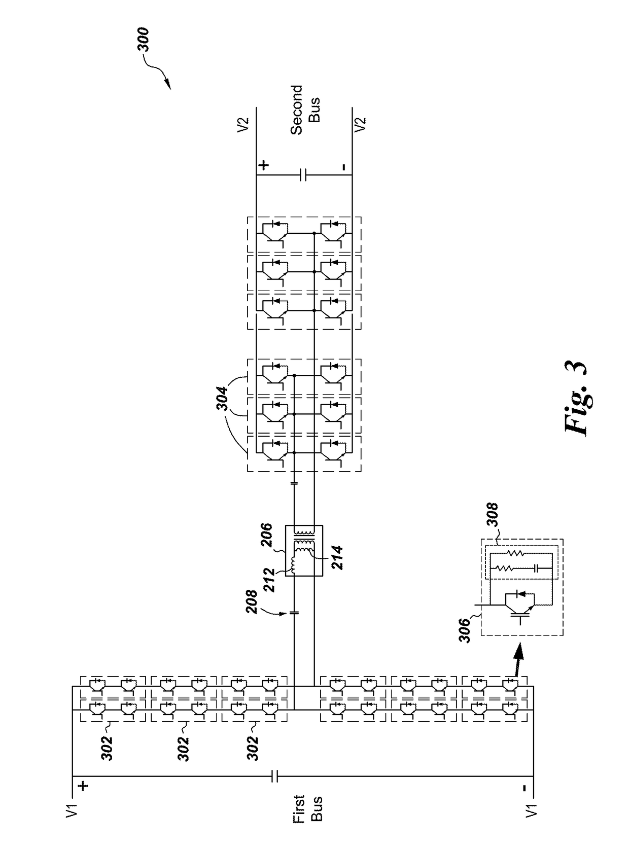
With the large number of semiconductor devices in series and their associated snubber circuit, conventional control method will lead to loss of soft switching and lower converter efficiency and consequently forcing a lower frequency and lower power density design.

Method used


Image

  • System and method for operating a DC to DC power converter
  • System and method for operating a DC to DC power converter
  • System and method for operating a DC to DC power converter

Examples


Embodiment Construction

[0017]Unless defined otherwise, technical and scientific terms used herein have the same meaning as is commonly understood by one of ordinary skill in the art to which this disclosure belongs. The terms “first”, “second”, and the like, as used herein do not denote any order, quantity, or importance, but rather are used to distinguish one element from another. Also, the terms “a” and “an” do not denote a limitation of quantity, but rather denote the presence of at least one of the referenced items. The term “or” is meant to be inclusive and mean one, some, or all of the listed items. The use of “including,”“comprising” or “having” and variations thereof herein are meant to encompass the items listed thereafter and equivalents thereof as well as additional items. The terms “connected” and “coupled” are not restricted to physical or mechanical connections or couplings, and can include electrical connections or couplings. The connections may include direct connections. Furthermore, the ...


PUM


Abstract

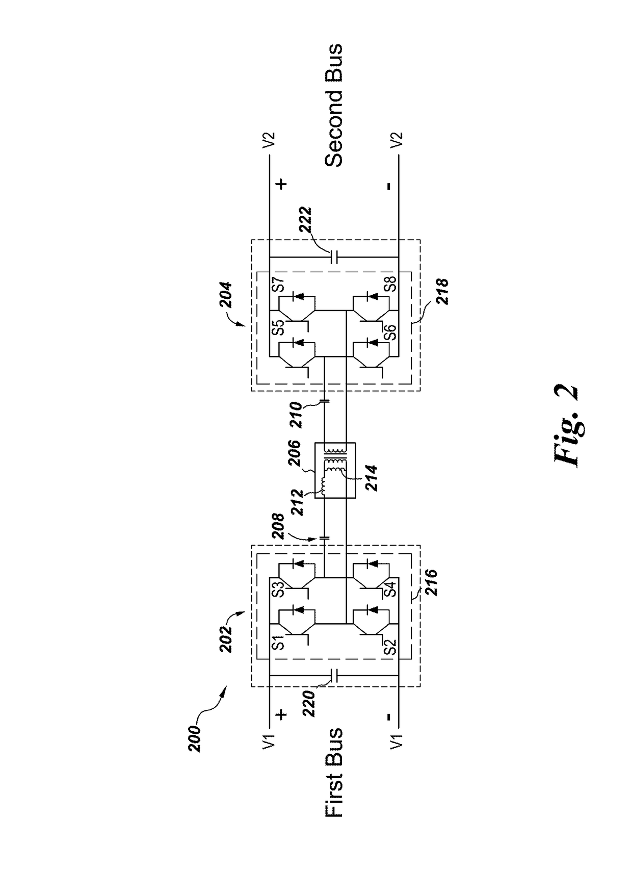
A direct current (DC) to DC power converter includes a first bus converter for converting a first DC bus voltage into a first high frequency AC voltage and a second bus converter for converting a second high frequency alternating current (AC) voltage into a second DC bus voltage. The DC to DC converter also includes a resonant circuit for coupling the first bus converter and the second bus converter and a controller for providing switching signals to the first bus converter and the second bus converter to operate the power converter in a soft switching mode. The controller includes a switching frequency controller for determining a switching frequency signal for the power converter based on a reference output current and a phase shift controller for determining a phase shift signal for the power converter. When the reference output current is lower than the a first load current value the switching frequency signal is maintained at a first switching frequency and the phase shift is determined according to the reference output current. Further, when the reference output current is above a second load current value the switching frequency signal is maintained at a second switching frequency and the phase shift is determined according to the reference output current. When the reference output current is between the first load current value and the second load current value, the switching frequency signal is adjusted according to a value of the reference output current and the phase shift is determined based on the switching frequency, the reference output current and perturbations in the output current.

Description

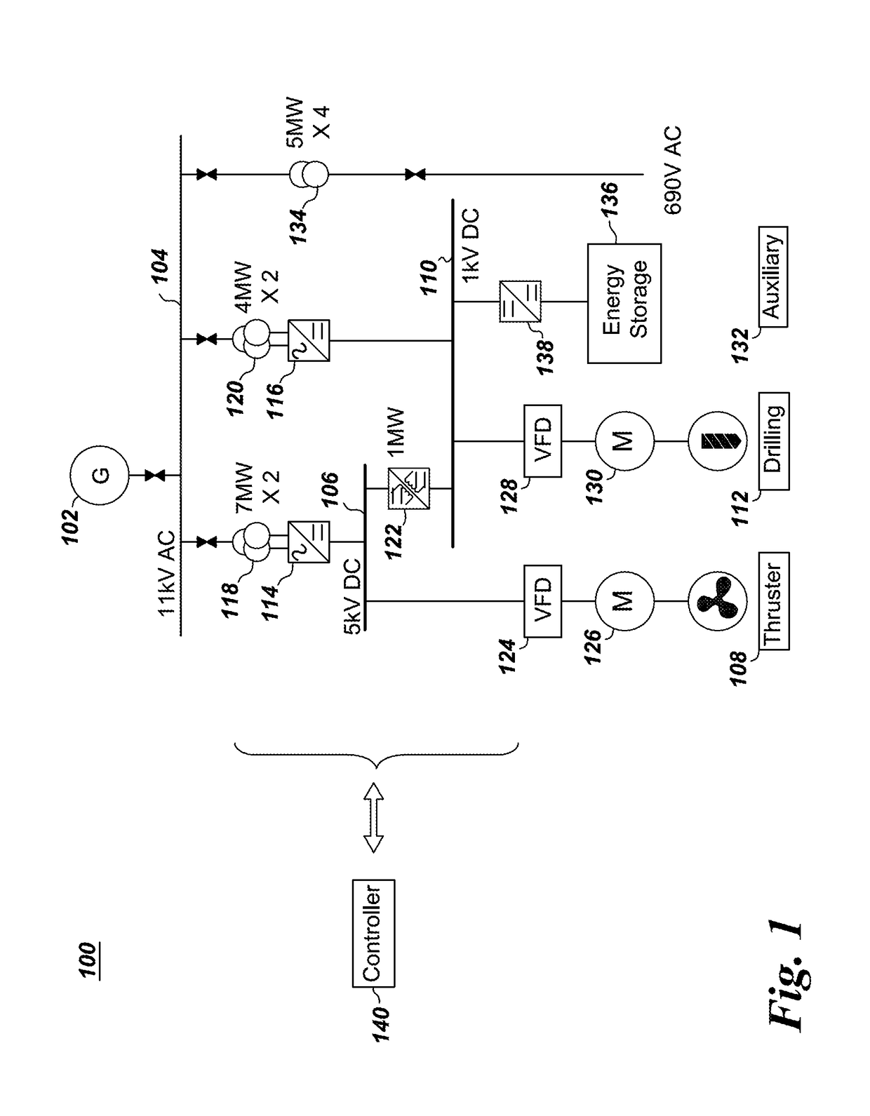
BACKGROUND[0001]Embodiments of the invention relate generally to power converters and more specifically to system and method for operating a direct current (DC) to DC power converter.[0002]DC to DC power converters are very prevalent in today's power system. There are many applications of DC to DC converters, e.g., power supplies for cell phones, laptops etc. Even in hybrid electric vehicles or military / civil aircrafts DC to DC converters may be used. For offshore applications, such as marine, there are variety of loads which may be fed by DC power supply. In such marine ships, many DC buses which are interconnected so as to transfer power therebetween may be utilized. The interconnections between DC buses require coupling the DC buses with DC to DC converters. Generally, the efficiency of the overall marine power architecture needs to be high which in turn requires highly efficient DC to DC converters. Thus, in many embodiments, soft switching is employed for controlling DC to DC c...

Claims


Application Information

Patent Timeline
Patent Type & Authority Patents(United States)
IPC IPC(8): H02M3/335H02M3/337H02M1/088H02M1/34H02M1/00
CPCH02M3/33584H02M1/088H02M3/3376H02M2001/348H02M2001/0058Y02B70/10H02M1/0058H02M1/348
Inventor AGAMY, MOHAMMEDDONG, DONGPAN, YANGARCES, LUIS JOSE
Owner GENERAL ELECTRIC CO
Learn More