Systems and methods for electrocorticography signal acquisition

a signal acquisition and electrocorticography technology, applied in the field of signal acquisition, can solve the problems of uneconomically large electronics footprint and impracticality of arrayed implementations beyond eight amplifiers

Active Publication Date: 2019-03-05
CORTERA NEUROTECH INC +1
View PDF15 Cites 6 Cited by
  • Summary
  • Abstract
  • Description
  • Claims
  • Application Information

AI Technical Summary

Benefits of technology

[0012]Accordingly, aspects of the present disclosure are novel circuit architectures and methods for electrocorticography (ECoG) or electroencephalography (EEG) or Action Potential signal acquisition that enable small area, low noise recording and digitization of brain signals from ECoG or EEG electrode arrays. The architectures and methods of the present disclosure enable conversion of microelectrode signals of interest into digital words using extremely low power and low area using a mixed-signal approach and implementation within a low-voltage environment.

Problems solved by technology

The main challenge in the design of such a subsystem is to provide low input-referred noise while avoiding loading excessively the high impedance electrodes and while preventing the large offset associated with the electrode-tissue interface from saturating the electronics.
Current solutions design the amplifying and digitizing functions separately and use large passive components, leading to an un-economically large footprint for the electronics.
While good power efficiencies have been achieved, the resulting die area per amplifier can make arrayed implementations beyond approximately eight amplifiers impractical.

Method used


Image

  • Systems and methods for electrocorticography signal acquisition
  • Systems and methods for electrocorticography signal acquisition
  • Systems and methods for electrocorticography signal acquisition

Examples


Embodiment Construction

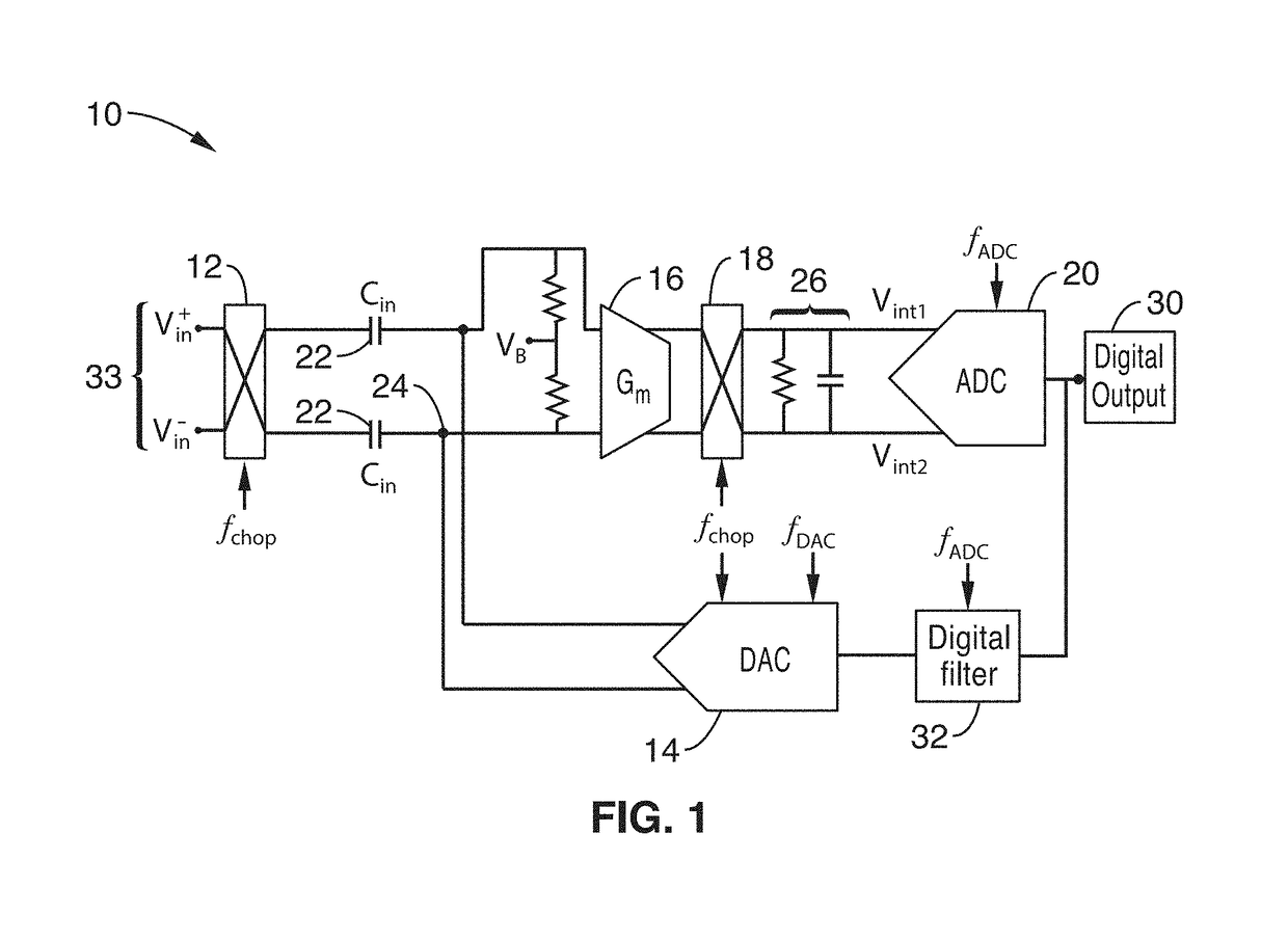
[0042]The present disclosure is directed to circuit architectures and methods for neurological and biological signal acquisition such as electroencephalography (EEG) electrocorticography (ECoG). By way of example and not of limitation, a functional block diagram for an improved architecture for an ECoG front-end (e.g. amplifier / digitizer system) 10 according to one embodiment of the invention is shown in FIG. 1.

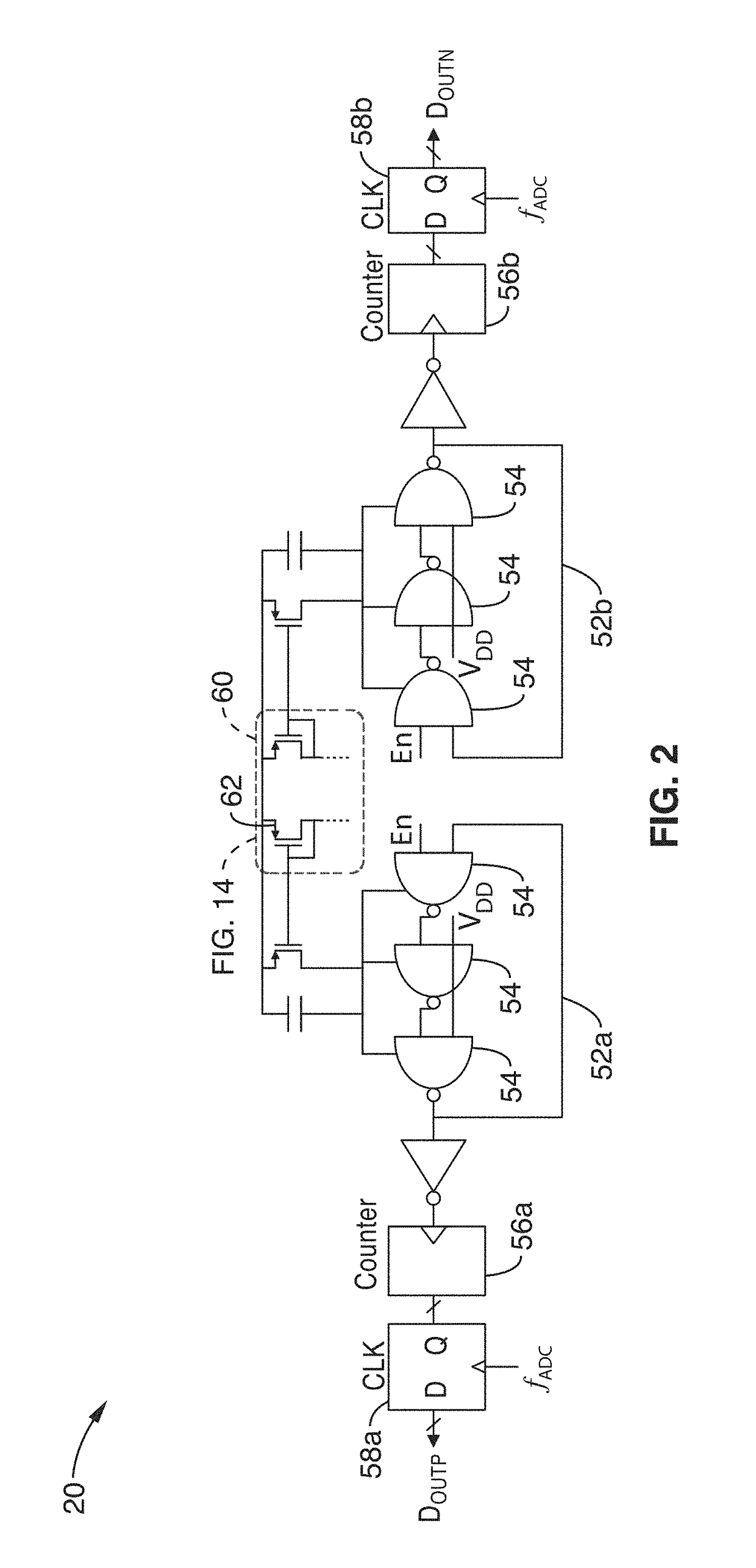
[0043]The ECoG front-end 10 illustrated in FIG. 1 generally comprises a chopper-stabilized, open-loop amplifier. The amplifier comprises input up-modulation chopper switches 12, a Gm stage 16, down-modulation chopper switches 18 and an R-C filter load 26. The output of the amplification stage 33 is connected to an ADC 20. In a preferred embodiment, the ADC 20 comprises a VCO-based ADC. Shown in greater detail in FIG. 2, VCO-ADC 20 uses a voltage to current converter to drive a ring oscillator 52a / 52b whose output is fed into a counter 56a / 56b for quantization. The quantizatio...


PUM


Abstract

Systems and methods for biosignal acquisition, and in particular, electrocorticography signal acquisition, are disclosed for small area, low noise recording and digitization of brain signals from electrode arrays.

Description

CROSS-REFERENCE TO RELATED APPLICATIONS[0001]This application is a 35 U.S.C. § 111(a) continuation of PCT international application number PCT / US2014 / 051959 filed on Aug. 20, 2014, incorporated herein by reference in its entirety, which claims priority to, and the benefit of, U.S. provisional patent application Ser. No. 61 / 867,899 filed on Aug. 20, 2013, incorporated herein by reference in its entirety. Priority is claimed to each of the foregoing applications.[0002]The above-referenced PCT international application was published as PCT International Publication No. WO 2015 / 026988 on Feb. 26, 2015, which publication is incorporated herein by reference in its entirety.STATEMENT REGARDING FEDERALLY SPONSORED RESEARCH OR DEVELOPMENT[0003]This invention was made with Government support under HR0011-07-3-0002 awarded by the Defense Advanced Research Projects Agency (DARPA). The Government has certain rights in the invention.INCORPORATION-BY-REFERENCE OF COMPUTER PROGRAM APPENDIX[0004]Not...

Claims


Application Information

Patent Timeline
Patent Type & Authority Patents(United States)
IPC IPC(8): A61B5/00A61N1/37A61B5/04A61B5/0476H04L27/06A61B5/048A61B5/0478A61B5/374
CPCA61B5/0006A61B5/04004A61B5/04017A61B5/0476A61B5/7228A61N1/3704H04L27/06A61B5/7203A61B5/0478A61B5/048A61B5/316A61B5/374A61B5/291A61B5/369A61B5/30
Inventor MULLER, RIKKY
Owner CORTERA NEUROTECH INC
Why Eureka
Try Eureka