Successive approximation digital voltage regulation methods, devices and systems

a digital voltage and approximation technology, applied in the field of digital voltage regulators, can solve the problems of insufficient digital load, inability to operate with such input voltages, and inability to regulate and stabilize digital voltage regulators, and achieve the effect of stable voltage regulator operation

Active Publication Date: 2019-03-05
RGT UNIV OF CALIFORNIA
View PDF12 Cites 2 Cited by
  • Summary
  • Abstract
  • Description
  • Claims
  • Application Information

AI Technical Summary

Benefits of technology

[0037]A preferred method for proportional derivative digital compensation of a voltage regulator includes generating an output voltage in a voltage regulator targeting a target voltage and eliminating an output pole of the voltage regulator to provide a stable voltage regulator operation irrespective of load current, load capacitance, or sampling frequency. The step of eliminating the output pole can avoid oscillatory behavior in response to the slope of the output achieving a correct polarity by discontinuing output approximation and allowing the compensation to stabilize the output voltage.

Problems solved by technology

Analog LDOs have difficulty operating with the which such input voltages because of low-voltage headroom.
However, the achievable response times are 44-4000 ns, which is insufficient for many digital loads.
Digital LDOs often suffer from limited dynamic range over which the load is regulated and stable, and the DLDOs occupy a large active area due to barrel-shifter-based control.
Typical prior DLDOs, like the one shown in FIG. 1, utilize a 2N unary-sized PMOS array driven through a 2N bit barrel-shifter that increments or decrements array conductance by a single (or a small number of) fingers per CLK cycle, resulting in a linear search over upwards of 2N cycles, which results in a 2N / N longer settling time than the proposed scheme.

Method used


Image

  • Successive approximation digital voltage regulation methods, devices and systems
  • Successive approximation digital voltage regulation methods, devices and systems
  • Successive approximation digital voltage regulation methods, devices and systems

Examples


Embodiment Construction

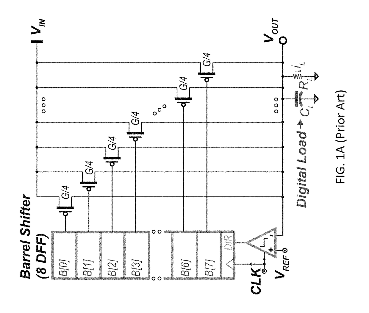
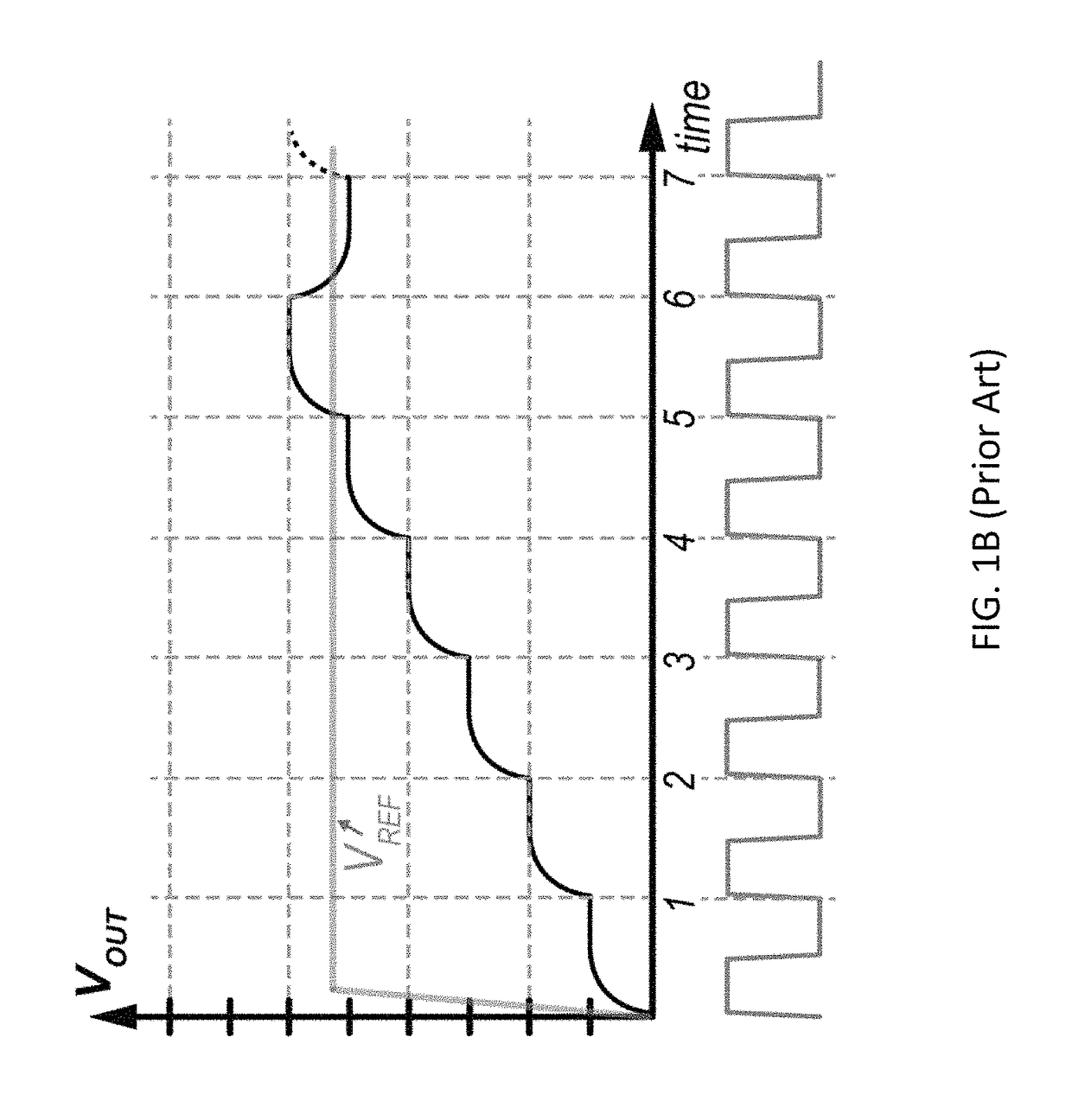
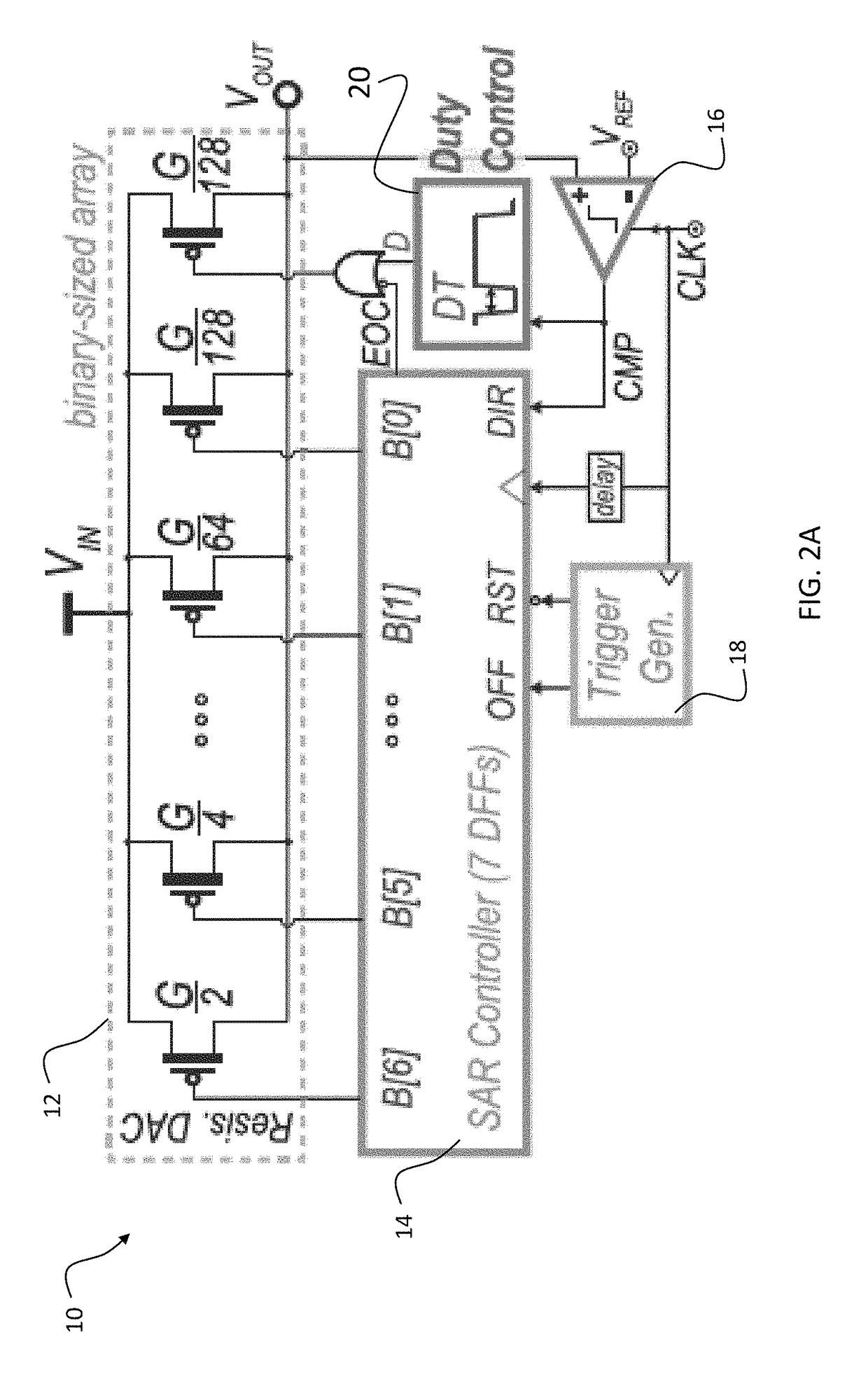
[0053]Preferred embodiments provide a recursive all-digital LDO (RLDO) circuits and methods that enable stable and pragmatic binary searches, and avoid large staircase overshoots / undershoots during binary search steps by operating from a clock whose frequency is faster than the time constant of the load. Stability is provided by a variable-coefficient proportional derivative compensation. Steady-state errors are avoided with hysteretic pulse width modulation (PWM) control that also enables sub-LSB (least significant bit) load current regulation. Loop-interruption logic avoids large overshoot / undershoot that can result from a sudden IL or ΔVIN step change occurs in during the binary search [after deciding the first few most significant bits (MSBs)].

[0054]A preferred embodiment recursive all-digital LDO (RLDO) consists of a binary weighted PMOS switch array controlled by a recursive successive approximation (SAR) controller that performs coarse regulation via a recursive binary search...


PUM


Abstract

A low power voltage regulator includes a weighted transistor array having a plurality of transistor switches with a total conductance of G, corresponding to bits from a MSB to LSB. A transistor switch corresponding to the MSB has a conductance of G / 2 and remaining bits have a consecutive descending conductance of G / 2.sup.N to the LSB, and search time takes a low number of cycles by starting with the MSB. A redundant LSB transistor switch has the same G / 2.sup.N conductance of the LSB. The redundant LSB is used to correct steady-state errors, and a proportional derivative controller compensates output voltage. The compensation in a method eliminates an output pole of the voltage regulator to provide a stable voltage regulator operation irrespective of load current, load capacitance, or sampling frequency. Voltage can be regulated via the additional LSB below the resolution limit via pulse width modulation.

Description

PRIORITY CLAIM AND REFERENCE TO RELATED APPLICATION[0001]The application claims priority under 35 U.S.C. § 119 from prior provisional application Ser. No. 62 / 454,221, which was filed Feb. 3, 2017, and incorporated by reference herein.STATEMENT OF GOVERNMENT INTEREST[0002]This invention was made with government support under DARPA HR0011-16-C-0037 awarded by the Defense Advanced Research Projects Agency. The government has certain rights in the invention.FIELD[0003]A field of invention is digital voltage regulators. Another field of the invention is system on a chip (SoC) systems. Other fields of the invention concern devices that included SoC systems, such as smailphones and tablets.BACKGROUND[0004]Modern sub-threshold SoC designs feature multiple power domains to dynamically track the maximum energy efficiency point (62 mV to 0.45V) in response to application demands. The following publications concern such designs.[0005]Y. Okuma et al., “0.5-V input digital LDO with 98.7% current ...

Claims


Application Information

Patent Timeline
Patent Type & Authority Patents(United States)
IPC IPC(8): H03M1/22H03M1/46G05F1/59H03M1/06H03M1/80
CPCH03M1/0617H03M1/462G05F1/59H03M1/808
Inventor SALEM, LOAI GALAL BAHGATMERCIER, PATRICK
Owner RGT UNIV OF CALIFORNIA
Why Eureka
Try Eureka