

Apparatus and method for controlling propagation and/or transmission of electromagnetic radiation in flexible waveguide(s)
a technology of electromagnetic radiation and electromagnetic radiation, applied in the direction of instruments, fibre light guides, cladded optical fibres, etc., can solve the problems of inability to determine the input to the fiber, the transfer function is no longer known, and the technique of conveying image information can be cumbersome and expensiv
- Summary
- Abstract
- Description
- Claims
- Application Information
AI Technical Summary
Benefits of technology
Problems solved by technology
Method used
Image

Examples
Embodiment Construction
[0008]To that end, to address at least such deficiencies, various exemplary embodiments of the present disclosure can be provided that can include and / or utilize one or more techniques for calculating or otherwise determining the transfer function of a multi-mode fiber based on its refractive index profile, twist, and bend.
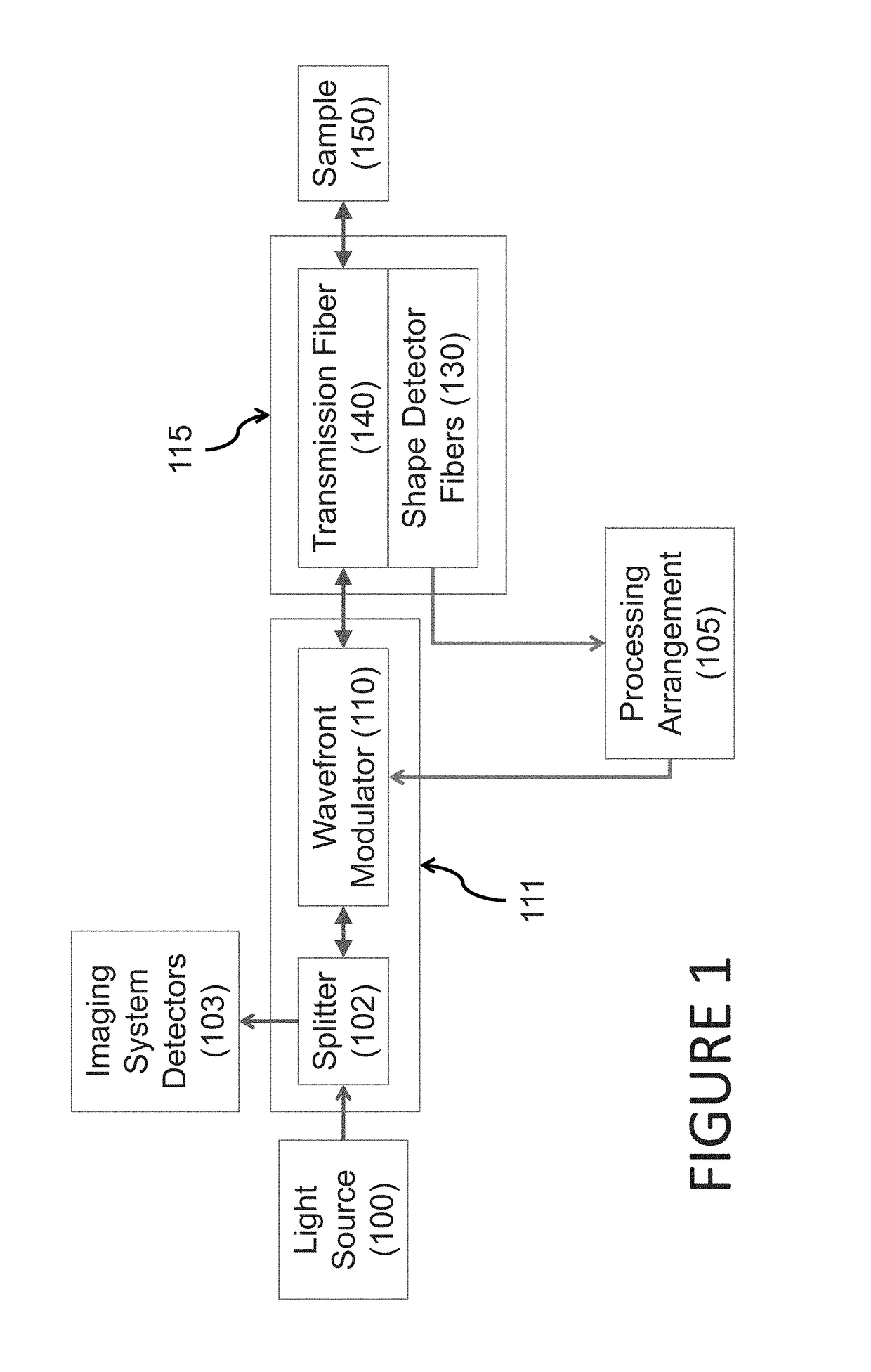
[0009]One of the objects of the present disclosure is provide and exemplary embodiment of as system which can be configured to focus light or other electro-magnetic radiation onto tissue of a subject using a multi-mode optical fiber system. According to another exemplary embodiment of the present disclosure, the system can include a light modulator and a waveguide apparatus. The waveguide apparatus can include one or more first waveguide regions for transmitting the light or other electromagnetic radiation to the subject and one or more second waveguide regions that can contain distributed sensors that can measure the shape of the fiber continually. In yet another...
PUM
 Abstract
Description
Claims
Application Information