System and method for detecting and defeating a drone

a technology of drones and systems, applied in direction finders using radio waves, process and machine control, instruments, etc., can solve problems such as unparallel flexibility and convenience, and achieve the effects of reducing interference risk, speeding up the detection process, and high energy conversion efficiency

Active Publication Date: 2019-03-19
CELLANTENNA INT INC
View PDF68 Cites 4 Cited by
  • Summary
  • Abstract
  • Description
  • Claims
  • Application Information

AI Technical Summary

Benefits of technology

[0013]In one of the preferred embodiments, the detection antenna array can include a set of four 90-degree sector antennas. The sector antennas are structured and configured to create a powerful antenna array station. The versatile combination of the sector antennas allows unparalleled flexibility and convenience, while using them to detect drones and drone signals. Furthermore, each sector antenna is structured to combine high gain with a wide 90° beam-width, which may be crucial in drone and drone control signal detection. As such, the sector antennas are designed primarily to detect a wide range of Industrial Scientific and Medical (ISM) bands and work efficiently in all-weather operations. Furthermore, each of the sector antennas further comprises an antenna gain. The gain of an antenna (antenna gain) can be generally defined as the ratio of the power required at the input of a lossless reference antenna to the power supplied to the input of the sector antennas to produce, in a given direction, the same field strength at the same distance. As a result, it is standard practice to use an isotropic radiator as the base reference antenna when measuring the antenna gain, preferably even in the case of sector antennas. Moreover, it is to be noted the reference antenna (isotropic radiator) is lossless and that it would radiate its energy equally in all directions. This ordinarily means that any gain of the antenna is compared to the isotropic radiator as its reference point. Chiefly, this means that the gain of the isotropic radiator is 0 decibels (dB). Additionally, it is also customary to use the unit dB (decibels) to measure antenna gain as it pertains to each of the sector antennas. Therefore, exemplifying this, the antenna gain for each of the sector antennas is selected from a group of ranges measured in decibels (dB). Accordingly, in at least one of preferred embodiments, the antenna gain can be selected from the range of between 10 decibels (dB) to 20 decibels (dB). Additionally, in one of the other preferred embodiments, the antenna gain can also be approximately 15 decibels (dB). Therefore, as it can be seen, it is preferred that each of the sector antennas is structured and configured to keep the antenna gain relatively high without affecting coverage.
[0045]Next, the override signal is transmitted from the transmission antenna connected to the neutralization system towards the source direction of the drone control signal. As aforementioned earlier, the override signal transmitted via the transmission antenna is replicated to match the detected drone signal. Alternatively, it can also be a protocol synthesized drone control signal aimed at the direction of the drone. As such, in one of the preferred embodiments, the override signal is configured to capture and direct the detected drone by controlling its operations, in case of signal loss or motor shut down. In other words, the override signal allows for the drone to be safely controlled and captured, when the override signal immediately disrupts or malfunctions the drone's existing drone control signal from its source. Similarly, the override signal transmitted by the transmission antenna is configured to suppress any existing drone control signals making it extremely cumbersome for its original operator to maintain control of the drone. In other words, the override signal offsets the drone control signal, relinquishing any and all of the drone's control from its original operator. Given this, the override signal takes over the drone's controls including its navigation capabilities so as to result in safe landing without any structural damages. As such, the override signal is configured to allow the renewed control of the drone to safely capture and land the drone to any given preferred destination. Accordingly, a series of override signals can be transmitted with specific protocols, continuously aimed towards the given drone, so as to ensure that any missing or unaffected codes are recognized and resulted. Thus, this allows for the override signal to effectively control, capture and land the drone according to plan. Consequently, in one of the preferred embodiments, to further compliment in controlling the drone, frequencies related to the drone's video links are also continuously relayed back and forth aimed at the drone, in order to get real time visual data as viewed via the drones cameras. As a result, this allows for a real-time visual with can further help in an effective control, capture and landing of the drone.

Problems solved by technology

The versatile combination of the sector antennas allows unparalleled flexibility and convenience, while using them to detect drones and drone signals.

Method used


Image

  • System and method for detecting and defeating a drone
  • System and method for detecting and defeating a drone
  • System and method for detecting and defeating a drone

Examples


Embodiment Construction

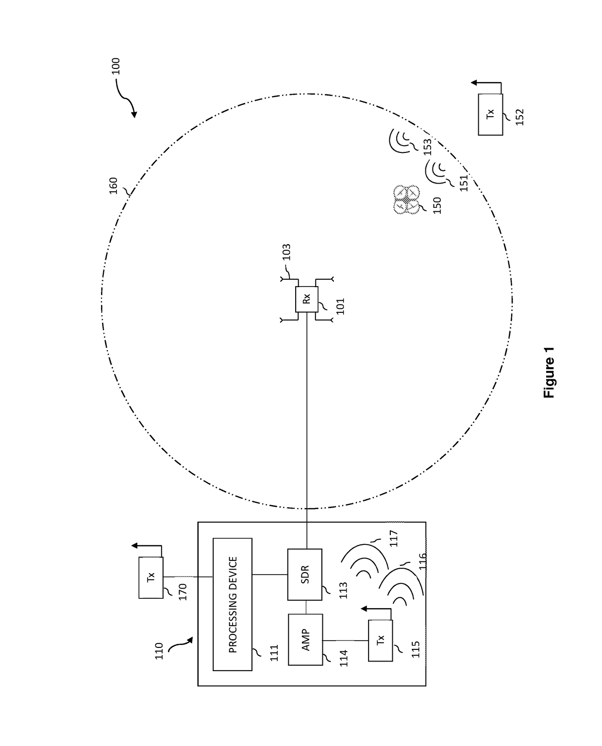
[0054]As shown in the accompanying drawings, the present invention is generally directed to a system and method for detecting and defeating a drone. More particularly, FIG. 1 illustrates a system 100 for detecting and defeating a drone 150. The system 100 generally includes a detection antenna array 101. The detection antenna array 101 generally is a set of two or more antennas and installed in various geometric arrays. In fact, in one of the preferred embodiments, the detection antenna array 101 includes a set of four 90-degree sector antennas 103. So then, each of the sector antennas 103 further comprises an antenna gain (not shown). The antenna gain is the ratio of the power required at the input of a loss-free reference antenna to the power supplied to the input of the given antenna to produce, in a given direction, the same field strength at the same distance. Given this, the antenna gain can be selected from a group of ranges in decibels (dB). The preferred ranges of the anten...


PUM


Abstract

A system for detecting and defeating a drone is disclosed which includes a detection antenna array configured to detect the drone and a control signal of the drone in a 360 degree field, the detection antenna array being further configured to detect the directionality of the drone with reference to the most dominant of the control signal of the drone detected by each of a plurality of antennas within the detection antenna array; a neutralization system disposed in communication with the detection antenna array; the neutralization system including a transmission antenna configured to transmit an override signal to the detected drone, an amplifier configured to modulate a gain of the override signal, and a processing device configured to generate the override signal and control transmission of the override signal.

Description

CLAIM OF PRIORITY[0001]The present application is a Continuation application which claims priority to U.S. Ser. No. 14 / 693,280 which was filed on Apr. 22, 2015 and which has matured into U.S. Pat. No. 9,529,360 on Dec. 27, 2016, which is based on and a claim of priority is made under 35 U.S.C. Section 119(e) to a provisional patent application that is in the U.S. Patent and Trademark Office, namely, that having Ser. No. 62 / 108,595 and a filing date of Jan. 28, 2015, all of which is explicitly incorporated herein by reference.BACKGROUND OF THE INVENTIONField of the Invention[0002]This invention generally relates to systems and methods of detecting and defeating a drone. More specifically, a drone within the range of a detection antenna array is detected, its control signal is captured, and a neutralization system then emits an override signal based on the captured control signal.Description of Related Art[0003]The use of drones besides the United States military has increased exponen...

Claims


Application Information

Patent Timeline
Patent Type & Authority Patents(United States)
IPC IPC(8): G05D1/00G01S3/46F41H13/00B64C39/02H04K3/00
CPCG05D1/0022G01S3/46F41H13/0093B64C39/024H04K3/60B64C2201/146H04K3/42H04K3/44H04K3/45H04K3/46H04K3/65H04K3/92H04K2203/14H04K2203/22H04K2203/32H04K3/94G01S3/023B64U2201/20
Inventor MELAMED, HOWARDMELAMED, STEVANSVANBERG, CHRISPONCE, MATIASHORVAT, MICHAEL
Owner CELLANTENNA INT INC
Why Eureka
Try Eureka