Steerable shape sensing biopsy needle

a biopsy needle and sensing technology, applied in the field of biopsy needles, can solve problems such as limited accuracy during insertion

Active Publication Date: 2019-03-26
INTELLIGENT FIBER OPTIC SYST
View PDF7 Cites 1 Cited by
  • Summary
  • Abstract
  • Description
  • Claims
  • Application Information

AI Technical Summary

Benefits of technology

[0011]A fifth object of the invention is a texture sensing catheter having one or more contact ridges which couple vibrations generated by movement of the contact ridge over a surface to be measured, thereby providing for the measurement of surface roughness.
[0013]In a biopsy needle embodiment of the invention, Fiber Bragg Grating (FBG) sensors reflect optical energy with a peak wavelength that shifts in proportion to the strain to which a particular FBG is subjected. The advantage of optical devices such as sensors and actuators which rely on optical fiber is they are inherently MRI-compatible, do not interact with the MRI image acquisition process, and do not cause significant imaging artifacts, thereby providing an ideal method of sensing the configuration and forces upon interventional devices in the MRI environment. FBG strain sensors of the present invention can resolve strains as small as 0.1 micro-strain and multiple FBG sensors can be located along a single fiber and addressed via optical multiplexing. In one embodiment of the present invention, FBG sensors are placed circumferentially about, and parallel to, the central axis, and strain gratings in the fibers are used to detect the deflection of a needle such as a biopsy needle for use in an MRI environment.

Problems solved by technology

The biopsy needle may have a plurality of strain sensors, and which may optionally incorporate actuation gratings for needle deflection sensing, is suitable for use in MRI-guided percutaneous needle biopsy and brachytherapy, in which MRI is used to plan needle placement, but is limited in accuracy during insertion due to needle deflections that commonly occur.

Method used


Image

  • Steerable shape sensing biopsy needle
  • Steerable shape sensing biopsy needle
  • Steerable shape sensing biopsy needle

Examples


Embodiment Construction

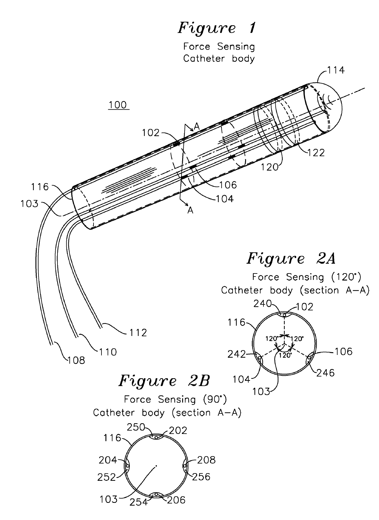
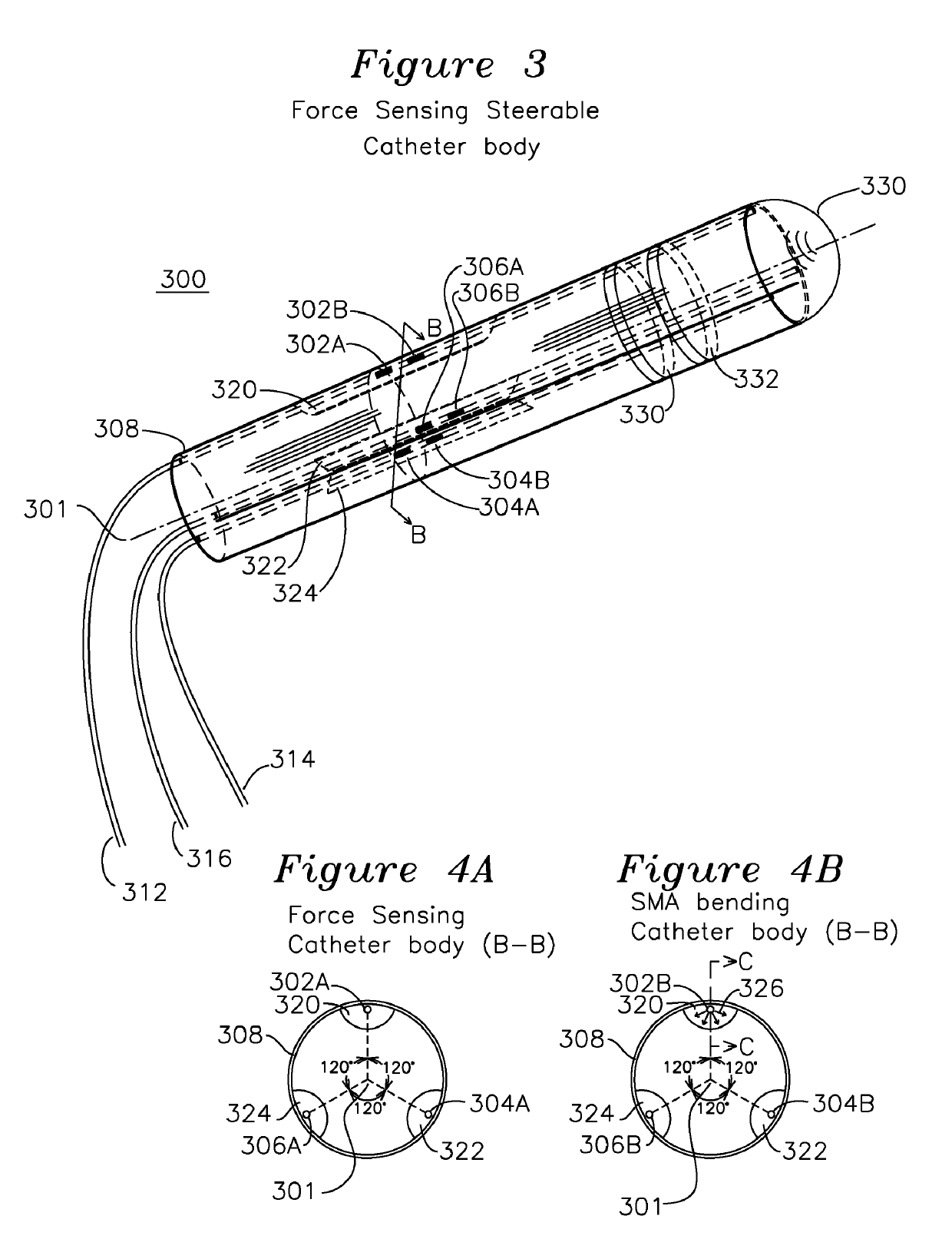
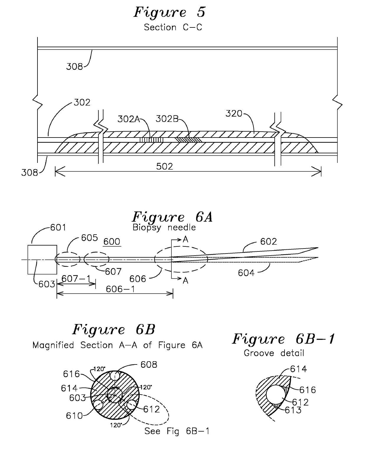
[0039]One aspect of the invention incorporates a plurality of optical fibers with fiber Bragg gratings (FBG) placed co-axially to form an MRI compatible biopsy needle, and in one embodiment, the outer needle sleeve 616 is a stock 18 gauge diameter×15 cm long biopsy needle, such as E-Z-EM model MR 1815, with an inner fiber locator 614 inserted in the needle sleeve 616 for guiding and shape sensing, which is removed for biopsy sampling. The FBG strain sensor can be located close to the base, where strain is concentrated in bending, or in another embodiment of the invention, the strain sensors can be in one or more axial extents and distributed circumferentially about the central axis and adjacent to an external sheath of the needle. In one embodiment of the invention, a first set of sensors is located a first distance from the needle base, and a second set of sensors is located a second distance from the needle base. In another embodiment of the invention, a series of FBGs are used as...


PUM


Abstract

A biopsy needle has a central axis and includes one or more sensing regions, each sensing region formed by a plurality of sensing optical fibers located over a particular extent of said central axis and inside the outer shell of the needle. The sensing optical fibers are coupled to a wavelength interrogator. A steerable catheter has a central axis and outer shell, the outer shell coupled to a plurality of optical fibers in sensing regions and actuation regions, the sensing regions formed over particular extents of the central axis by bonding gratings to the inner surface of the outer shell, and the actuation regions formed by coupling optical energy into shape memory alloys bonded to the outer shell.

Description

PRIORITY CLAIM[0001]The present patent application claims priority of U.S. Provisional Patent Application 61 / 175,399 filed May 4, 2009, and U.S. patent application Ser. No. 12 / 562,855 filed Sep. 18, 2009.[0002]This invention was made with government support under NIH Phase I SBIR grant number 1R43HL092771-01, “Fiber Optic Sensorized Tools for Cardiology Applications”, and the USAMRAA Phase I STTR Contract No.: W81XWH-08-C-0103, “MRI-Compatible Fiber-Optically Sensorized Surgical Tools for Precision Removal of Solid Tumors”. The government has certain rights in this invention.FIELD OF THE INVENTION[0003]The present invention relates to a biopsy needle, and is extendable to a catheter. In particular, the invention is related to a biopsy needle which can be steered while entering the body as well as after entering the body, and which generates an optical measurement which can be read and converted to an estimate of needle shape and optionally location using a strain-sensitive optical g...

Claims


Application Information

Patent Timeline
Patent Type & Authority Patents(United States)
IPC IPC(8): A61B10/02A61B17/00A61B90/00A61B34/20
CPCA61B10/0266A61B2017/003A61B2090/065A61B2034/2061A61B2017/00106
Inventor PARK, YONG-LAEBLACK, RICHARD JAMESMOSLEHI, BEHZADCUTKOSKY, MARK R.ELAYAPERUMAL, SANTHIDANIEL, BRUCEYEUNG, ALANSOTOUDEH, VAHID
Owner INTELLIGENT FIBER OPTIC SYST
Why Eureka
Try Eureka