
Method and system for monitoring fluid flow in a conduit

a conduit and fluid flow technology, applied in the field of method and system for monitoring fluid flow in a conduit, can solve the problems of inability to install and calibrate delta-p (p) sensors in oil and/or gas production or fluid injection wells, many existing flowmeters are costly pieces of equipment that are difficult to install, and many existing flowmeters are costly pieces of equipmen

Active Publication Date: 2019-03-26
SHELL USA INC
View PDF11 Cites 0 Cited by
  • Summary
  • Abstract
  • Description
  • Claims
  • Application Information

AI Technical Summary

Benefits of technology

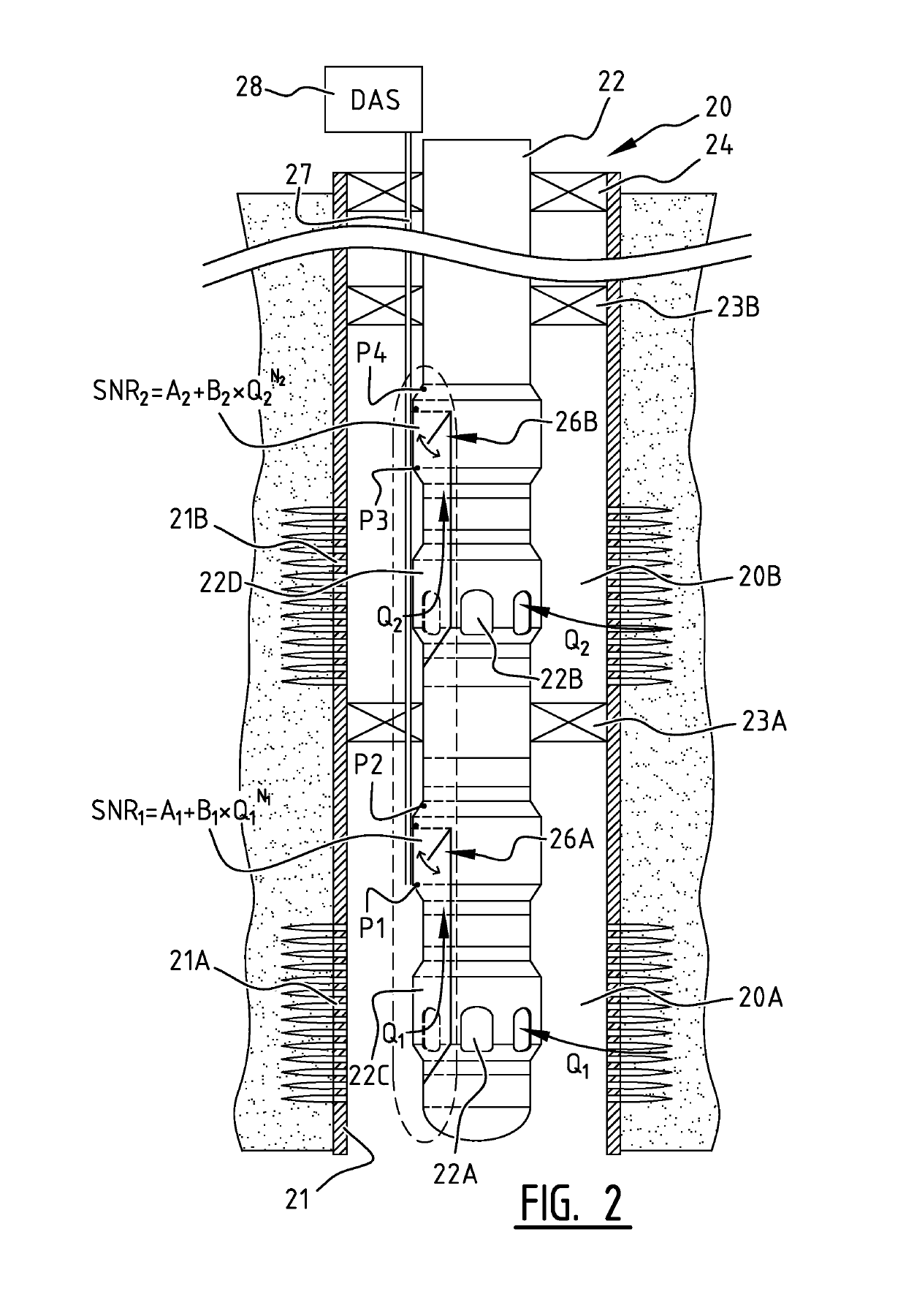
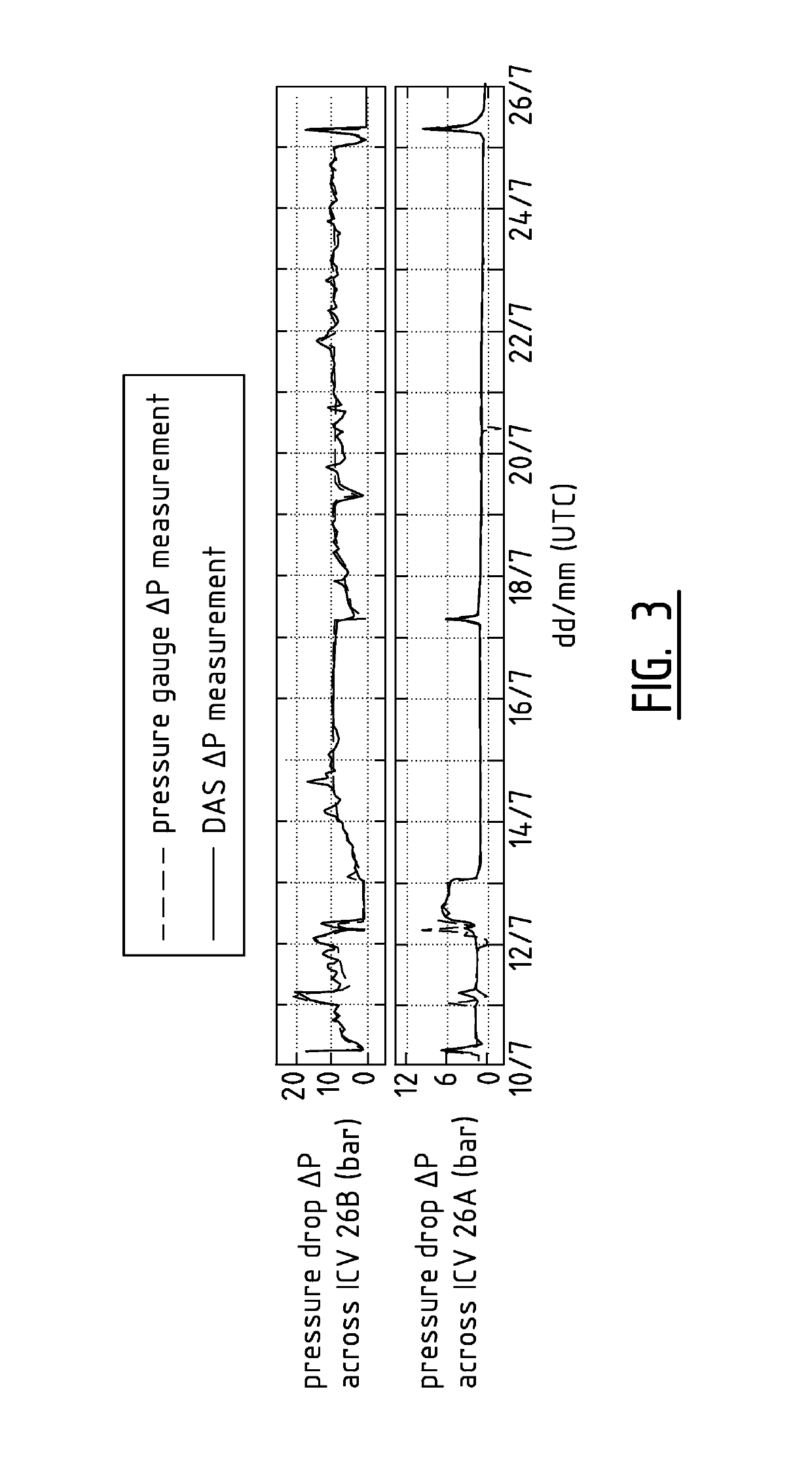
[0047]Further advantages of the method and system according to the invention are that DAS is extremely sensitive in picking up thermal and acoustic noise, allowing a small beta (large inner diameter of the venturi and low pressure drop) offering no objection for well intervention tools like Production Logging Tools. Secondly, the DAS measurement is a direct and single measurement from which the flowrate can be derived. Thirdly, the dynamic range of DAS is very large, large enough to cover the full range of Delta-P's. Fourthly, only a single optical fibre is required on which (an almost unlimited number of) venturi-meters can be multi-dropped. Fifthly, the combination of two venturi's in series and associated sensitive DAS assemblies may reveal information about gross and WC (watercut) and or the GVF (Gas-Volume-Fraction) in a multiphase flow in downhole well tubings and / or other multiphase fluid transportation tubulars.

Problems solved by technology

Many existing flowmeters are costly pieces of equipment that are difficult to install in a confined space, such as downhole in an oil and / or gas production or in a fluid injection well.
However, the installation and calibration of such a flowmeter in an oil and / or gas production or in a fluid injection well is still a complex and costly operation.
A further disadvantage of existing in-well venturi flowmeters is that delta-P (Δp) sensors are not available for downhole use and that therefore absolute pressure gauges to be installed upstream and downstream of each venturi meter.
The consequence is that to derive at a downhole delta-P (Δp) measurement two large numbers have be subtracted which is a large source of inaccuracy.

Method used


Image

  • Method and system for monitoring fluid flow in a conduit
  • Method and system for monitoring fluid flow in a conduit
  • Method and system for monitoring fluid flow in a conduit

Examples


Embodiment Construction

[0030]FIG. 1 is a schematic longitudinal sectional view of an oil and / or gas production well 1.

[0031]The well 1 comprises a well casing 2 which is cemented within a surrounding subsurface earth formation 3. The formation 3 comprises two oil and / or gas bearing layers 3A and 3B and the well casing 2 is perforated by an upper assembly of perforations 2A and a lower assembly of perforations 2B to facilitate influx of crude oil and / or natural gas from these layers 3A and 3B into the interior of the well 1, as illustrated by arrows 4A and 4B.

[0032]A production tubing 5 is suspended from a wellhead 6 into the well 1 and is sealingly connected to the well casing 2 by a pair of packers 7 and 8 that are located adjacent to the upper rims of the oil and / or gas bearing formation layers 3A and 3B, so that an annular space 9 between the production tubing 5 and well casing 2 is divided into an upper annular space 9A, an intermediate annular space 9B and a lower annular space 9C.

[0033]Crude oil and...


PUM


Abstract

A method for monitoring fluid flow in a conduit comprises:acoustically coupling an optical fiber to the conduit adjacent one or more flow restrictions (R1-R4) in the conduit;inducing a Distributed Acoustic Sensing (DAS) assembly to measure an acoustic noise signature (SNR1-4) generated in the fiber by the fluid flowing through each flow restriction (R1-R4);deriving the fluid flow rate of the fluid (QI, QI+II) flowing through each flow restriction (R1-R4) from the measured acoustic noise signature (SNR1-4); anddisplaying the derived fluid flow rate (QI, QI+II) at a fluid flow rate monitoring display.

Description

BACKGROUND OF THE INVENTION[0001]The invention relates to a method and system for monitoring fluid flow in a conduit.[0002]A variety of flowmeters is currently available to monitor fluid flow in a conduit. Many existing flowmeters are costly pieces of equipment that are difficult to install in a confined space, such as downhole in an oil and / or gas production or in a fluid injection well.[0003]It is known from U.S. Pat. No. 6,378,380 to monitor in such case fluid flow by measuring a pressure difference across a flow restriction in the conduit. However, the installation and calibration of such a flowmeter in an oil and / or gas production or in a fluid injection well is still a complex and costly operation.[0004]A further disadvantage of existing in-well venturi flowmeters is that delta-P (Δp) sensors are not available for downhole use and that therefore absolute pressure gauges to be installed upstream and downstream of each venturi meter. The consequence is that to derive at a downho...

Claims


Application Information

Patent Timeline
Patent Type & Authority Patents(United States)
IPC IPC(8): E21B47/10G01H9/00E21B47/12G01F1/708G01F1/7086
CPCE21B47/101E21B47/102G01F1/7086G01H9/004E21B47/123G01V2210/1429E21B47/107E21B47/113E21B47/135G01F1/712
Inventor IN 'T PANHUIS, PETRUS HENDRIKUS MARIA WILHEMUSDEN BOER, JOHANNIS JOSEPHUSKUSTERS, ROEL MARIEROY, DAYEETAMUSTAFINA, DARIA
Owner SHELL USA INC
Learn More