Linear induction motor plunger lift

a technology of plunger lift and induction motor, which is applied in the direction of fluid removal, borehole/well accessories, sealing/packing, etc., can solve the problems of reducing the output of well, increasing the loading of well, and insufficient gas flow rate, so as to reduce the force, less energy consumption, and low maintenance cost

Active Publication Date: 2019-04-02
CONOCOPHILLIPS CO
View PDF11 Cites 2 Cited by
  • Summary
  • Abstract
  • Description
  • Claims
  • Application Information

AI Technical Summary

Benefits of technology

[0013]Direct linear electro-mechanical energy conversion devices offer numerous advantages over their rotary-to-linear counterparts, notably the absence of mechanical gears and transmission systems, which results in a higher dynamic performance and improved reliability. The concept also lends itself to automation for quickly optimizing and maintaining the process at peak efficiency.
[0015]With this type of system, currently un-producible wells may actually be pumped free of liquids and restored to production. This process will insure the maximum hydrocarbon recovery from an oil and gas well and capture previously un-producible hydrocarbons.
[0020]In the case of this disclosure, the plunger or possible series of plungers represent the train while the tubing represents the track. Compared to a linear induction train track, a series of electromagnets are in this case installed along the production tubing. The plunger(s) itself is designed with e.g., annular electro and / or fixed magnets that are induced by the application of electrical voltage to the tubing or field magnets causing movement of the plunger. The field can also be annular, but like the plunger, magnets do not have to be annular. The repelling and attraction sequence between the tubing or field magnets and the plunger (rotor for a conventional rotary electric motor) magnets creates movement as with a common electric motor. The use of ring or annular magnets allows for an even or centralized application of the magnetic force, minimizing drag and friction effects that would reduce efficiency. However, the same effect could be achieved with other magnet shapes or magnet that are placed equidistantly around the circumference of the tubing and plunger lift device.
[0021]One distinct advantage of this plunger lift system is the ability to accelerate the plunger downhole by reversing the current to the field magnets, effectively decreasing the overall cycle time to pump the liquid. Applied voltage may also be adjusted to control the ascent and descent speed and force of the plunger for fine tuning the system. As with conventional plunger lift systems, this process may be automated, even to the point of applying artificial intelligence, to maintain peak efficiency for changing liquid loading conditions. Another feature of this method is that conventional gas pressure (if available) may be used along with the electrical energy to move the plunger, maximizing the amount of energy available to translate the plunger.
[0025]In all these topologies, the armature could be either air- or iron-cored, in which case it could be either slotless or slotted, while one member may be longer than the other dependent on the required stroke. Generally, the preferred topology depends on the application. Slotted iron-cored topologies usually have a higher force density, but may also produce an undesirable destabilizing tooth ripple cogging force and have the highest eddy current losses in the magnets and the iron, especially when operating at high speed. Slotless armature topologies, on the other hand, eliminate the tooth ripple cogging effect, and thereby improve the dynamic performance and servo characteristic at the expense of a reduction in specific force capability, although the cogging force associated with the finite length of the iron-cored armature may still be significant if it is not designed accordingly.

Problems solved by technology

However, at some point the flow rate of gas will be insufficient to carry liquids out of the well.
As a result, the liquid loading in the well will increase, and liquid will collect in the bottom of the well, further reducing its output.
A well without a deliquification technique will stop flowing or slow down and become a non-productive well, long before a properly deliquified well will.

Method used


Image

  • Linear induction motor plunger lift
  • Linear induction motor plunger lift
  • Linear induction motor plunger lift

Examples


Embodiment Construction

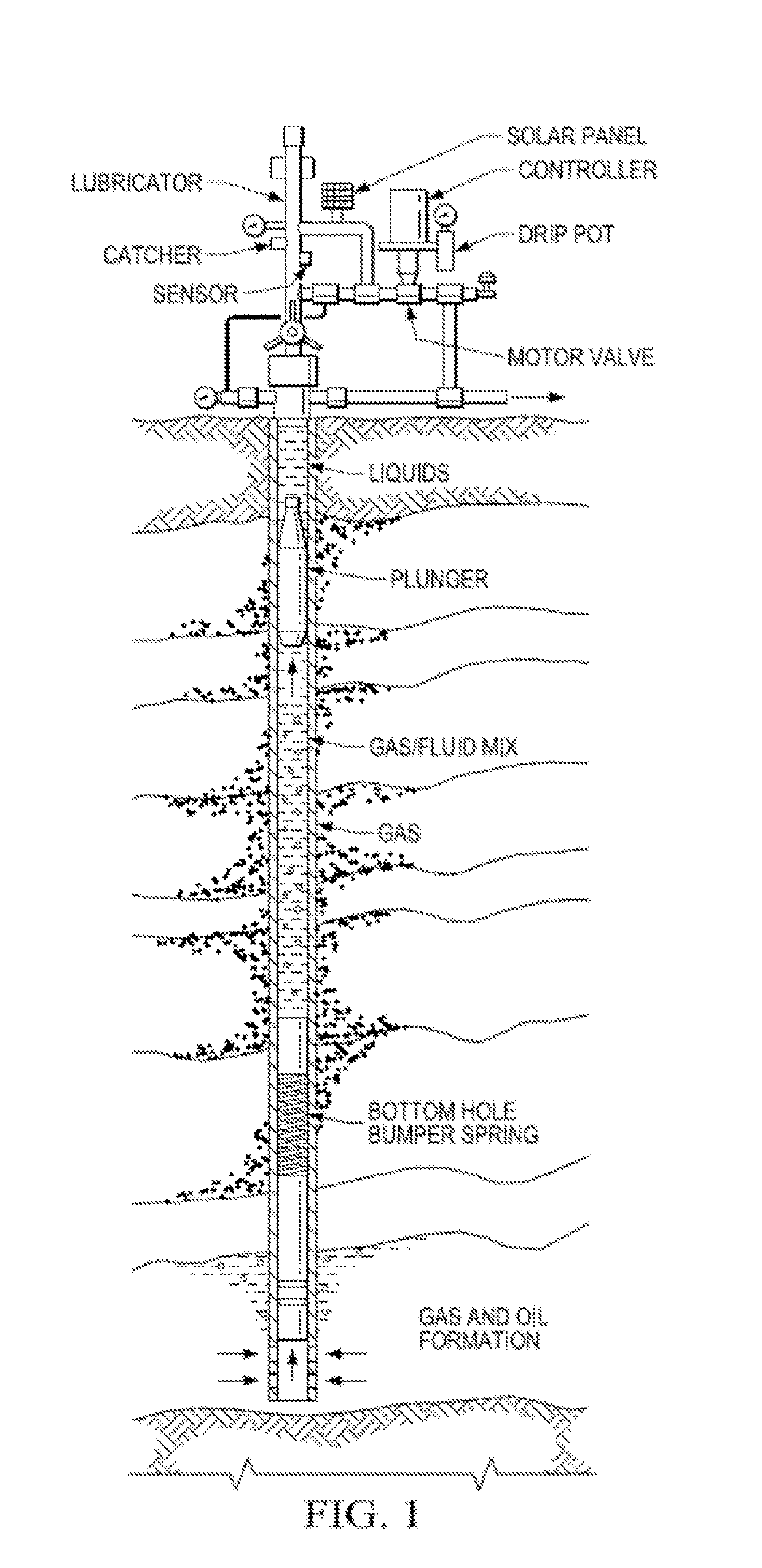
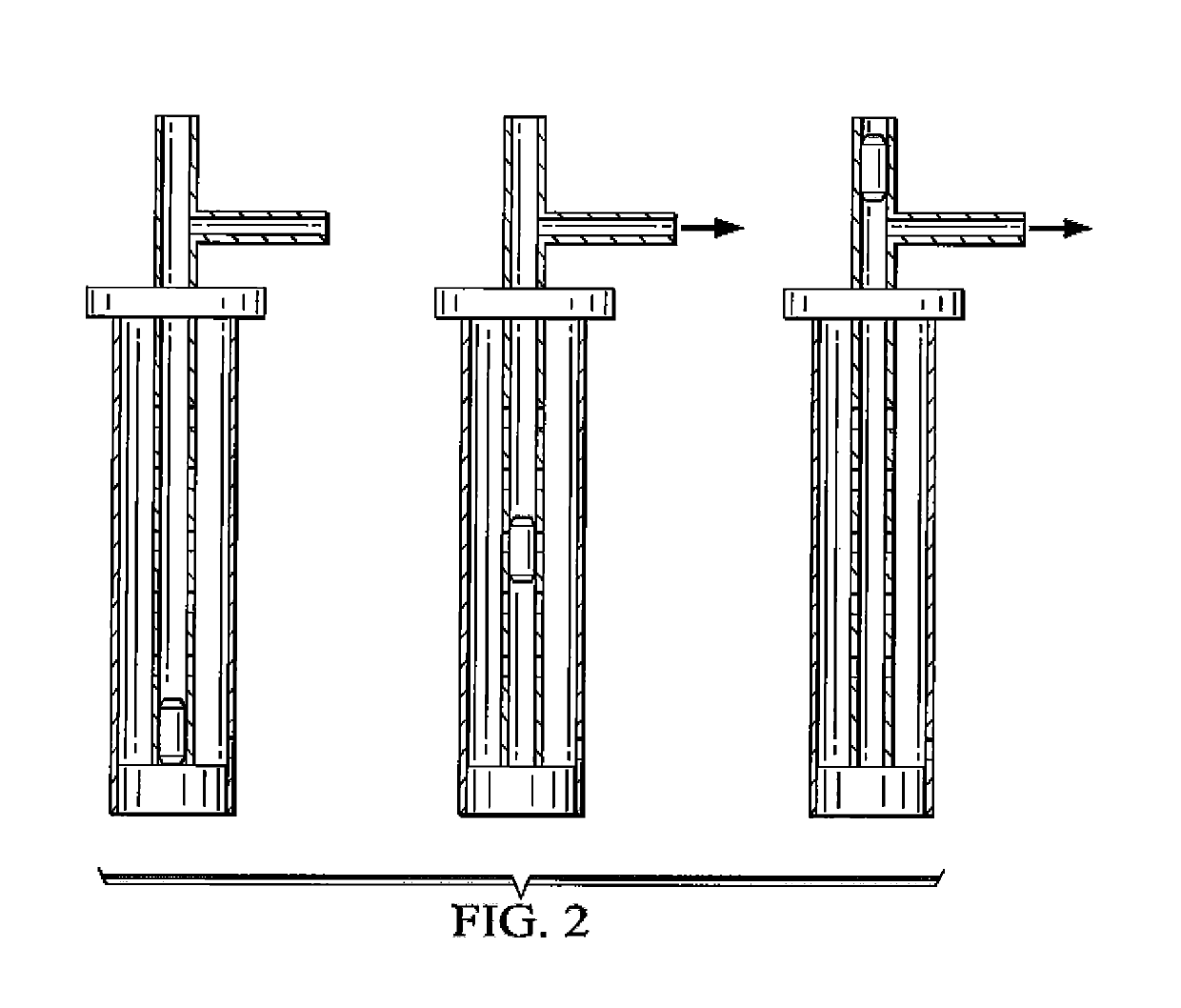
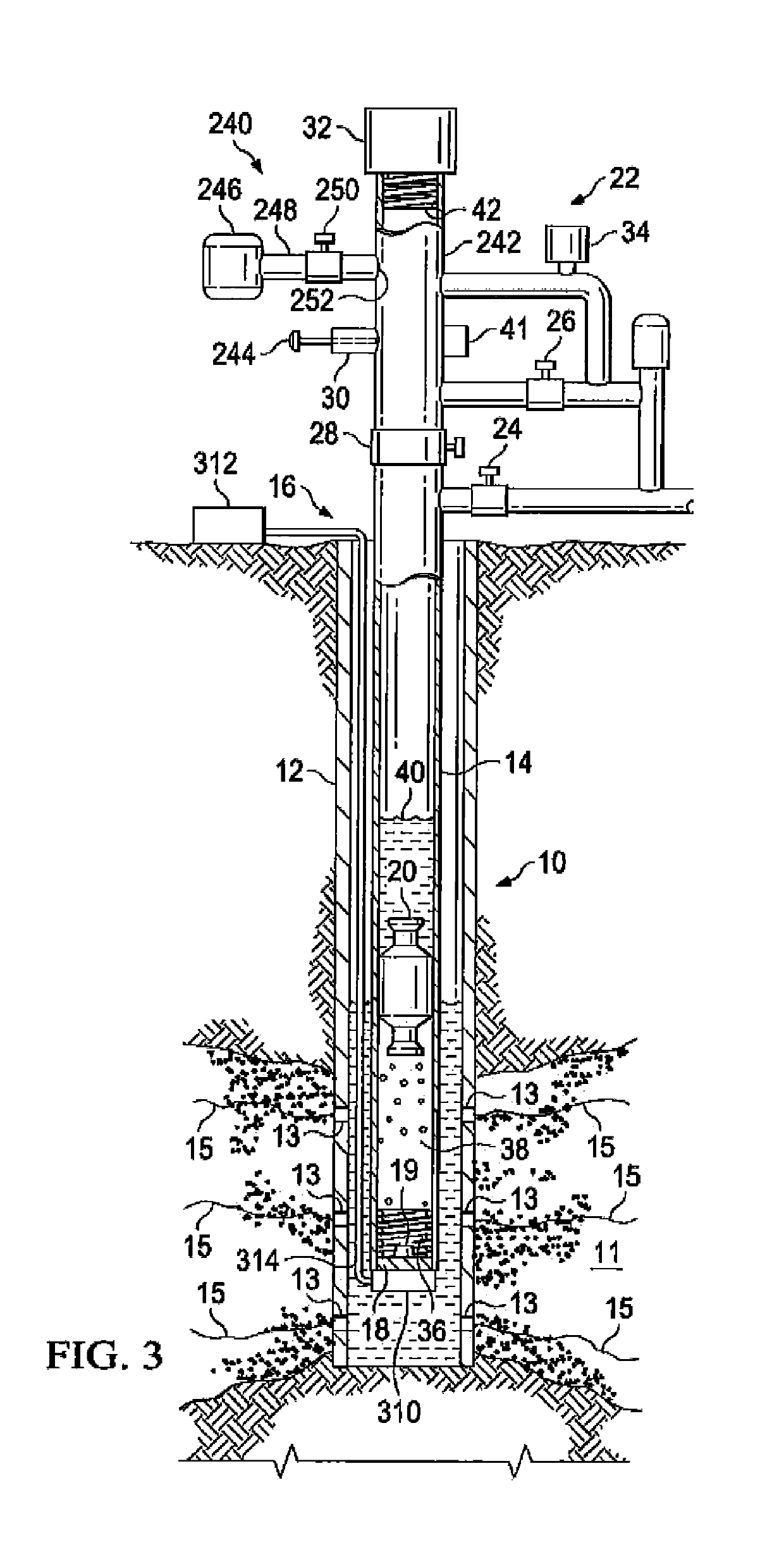
[0045]The disclosure provides one or more of the following embodiments in any combination thereof:[0046]An improved plunger lift system, the plunger lift system having a cased well, a plunger in the cased well moveable from a stop at the bottom of the cased well to a top of the cased well, thus delivering fluids to a wellhead, wherein plunger lift force is provided by a fluid pressure in said well, wherein the improvement comprises replacing said fluid pressure plunger lift force with a linear induction motor (LIM) plunger lift force.[0047]An improved plunger lift system wherein said LIM is a tubular linear induction motor (TLIM).[0048]An improved plunger lift system wherein said LIM also drives the plunger down said tubing at a speed faster than gravity drop speed.[0049]An improved plunger lift system, wherein the plunger lift system having a tubing positioned in a cased well, a plunger in the tubing moveable from the bottom of the tubing to a top of the tubing, wherein plunger lif...


PUM


Abstract

A plunger lift system that uses a linear induction motor instead of gas or fluid pressure to lift the plunger. Electrical voltage is applied to electromagnets installed along the tubing of a wellbore that will induce magnets contained within a special plunger that is introduced inside the tubing to move it and allow it to lift liquids with a piston-like action. The electromotive force may be adjusted by varying the applied voltage as needed to lift the column of liquid from the wellbore or the current reversed to accelerate and optimize plunger descent.

Description

PRIOR RELATED APPLICATIONS[0001]This application is a US Non-provisional Application, which claims the benefit of and priority to U.S. Provisional Application Ser. No. 62 / 108,340 filed Jan. 27, 2015. This application is incorporated herein by reference in its entirety for all purposes.FEDERALLY SPONSORED RESEARCH STATEMENT[0002]Not applicable.FIELD OF THE DISCLOSURE[0003]The disclosure generally relates to an improved plunger lift system based on linear induction principles.BACKGROUND OF THE DISCLOSURE[0004]As natural gas is produced from gas wells, the pressure in the formation will decrease, resulting in a reduction in gas flow rate and associated gas velocity. Before the natural drive pressure is reduced, the flow rate and velocity of produced gas may be sufficient to remove the liquids from the well with the gas. However, at some point the flow rate of gas will be insufficient to carry liquids out of the well. As a result, the liquid loading in the well will increase, and liquid...

Claims


Application Information

Patent Timeline
Patent Type & Authority Patents(United States)
IPC IPC(8): E21B43/00E21B43/12E21B34/06
CPCE21B43/121E21B43/128
Inventor DECARLO, LEONARD J.
Owner CONOCOPHILLIPS CO
Why Eureka
Try Eureka