
Purification of ultra-high saline and contaminated water by multi-stage ion concentration polarization (ICP) desalination

a technology of ion concentration polarization and desalination, which is applied in water treatment multi-stage treatments, electrodialysis, separation processes, etc., can solve the problems of large membrane area, rapid increase of total power consumption, poor area efficiency, etc., and achieve high salinity and cost reduction

Active Publication Date: 2019-04-09
MASSACHUSETTS INST OF TECH
View PDF7 Cites 0 Cited by
  • Summary
  • Abstract
  • Description
  • Claims
  • Application Information

AI Technical Summary

Benefits of technology

[0010]ICP technology can be economically developed for purification of produced water through trifurcated or bifurcated strategies comprising serial extraction of concentrate streams. These methods are advantageous to high salinity waters, offering significant cost reduction over existing technologies for pre and post treatment (e.g. elimination of suspended solids).

Problems solved by technology

According to this analysis, one can clearly find current flux through the membrane decreases along the membrane, thereby meaning most of ionic current flow in the earlier region of the membrane while later region of membrane does not contribute effective salt removal much.
Consequently, we need enormous membrane area (but, with poor area efficiency) to remove most of salts in feed solution especially when we treat high saline water.
As shown in FIG. 5(B), EPIR is increasing almost linear to the salt removal ratio in single-stage ICP, thereby meaning higher salt removal in single-stage should cause rapid increment of total power consumption.

Method used


Image

  • Purification of ultra-high saline and contaminated water by multi-stage ion concentration polarization (ICP) desalination
  • Purification of ultra-high saline and contaminated water by multi-stage ion concentration polarization (ICP) desalination
  • Purification of ultra-high saline and contaminated water by multi-stage ion concentration polarization (ICP) desalination

Examples


Embodiment Construction

A description of preferred embodiments of the invention follows.

Desalination and Purification for Seawater / Produced Water

[0023]Previously, we demonstrated ICP desalination using brackish (low saline) water. In order to verify the feasibility for highly concentrated water, we have carried out desalination experiments with natural seawater (from Revere Beach, Mass.) and high saline water (NaCl 1.0 M, similar salinity of typical flowback / produced water). FIG. 2A and FIG. 2B are visualizations of ICP desalination operation between two CEMs using natural seawater and high saline water, respectively, enhanced by adding small amounts of fluorescent dye to the feed solution. For monitoring real-time change of salt concentration in the dilute stream, we traced the conductivity value of desalted channel directly by connecting a flow-through conductivity probe (Microelectrode Inc., Bedford, N.H.). As shown in FIGS. 2A and 2B, the dark region, which actually means fluorescent dye-depleted regio...


PUM

PropertyMeasurementUnit
lengthaaaaaaaaaa
lengthaaaaaaaaaa
lengthaaaaaaaaaa

Abstract

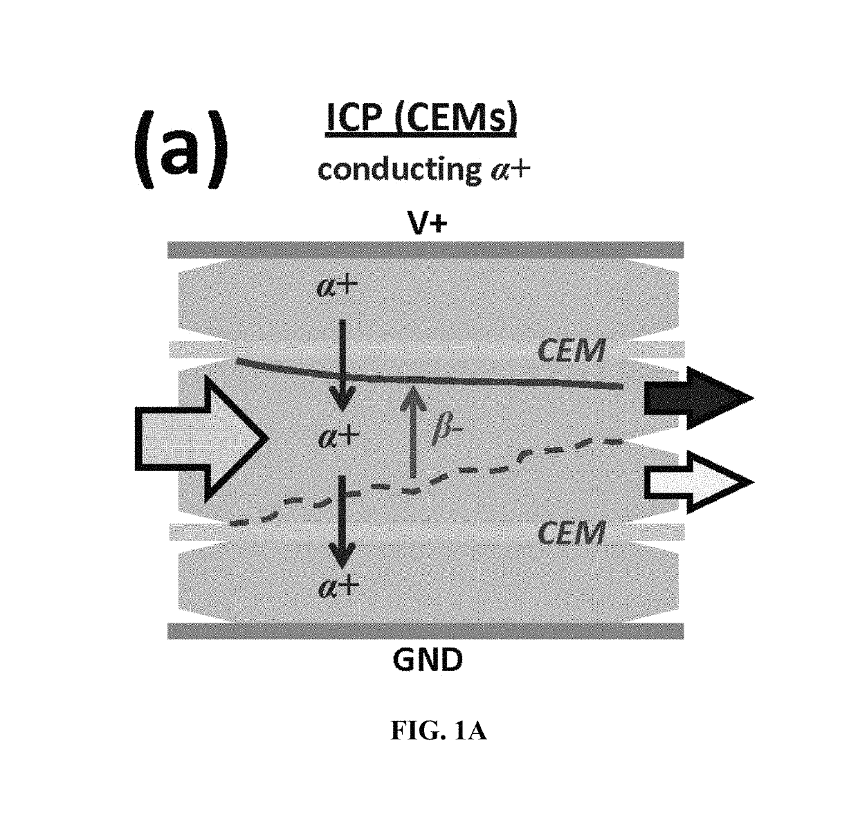
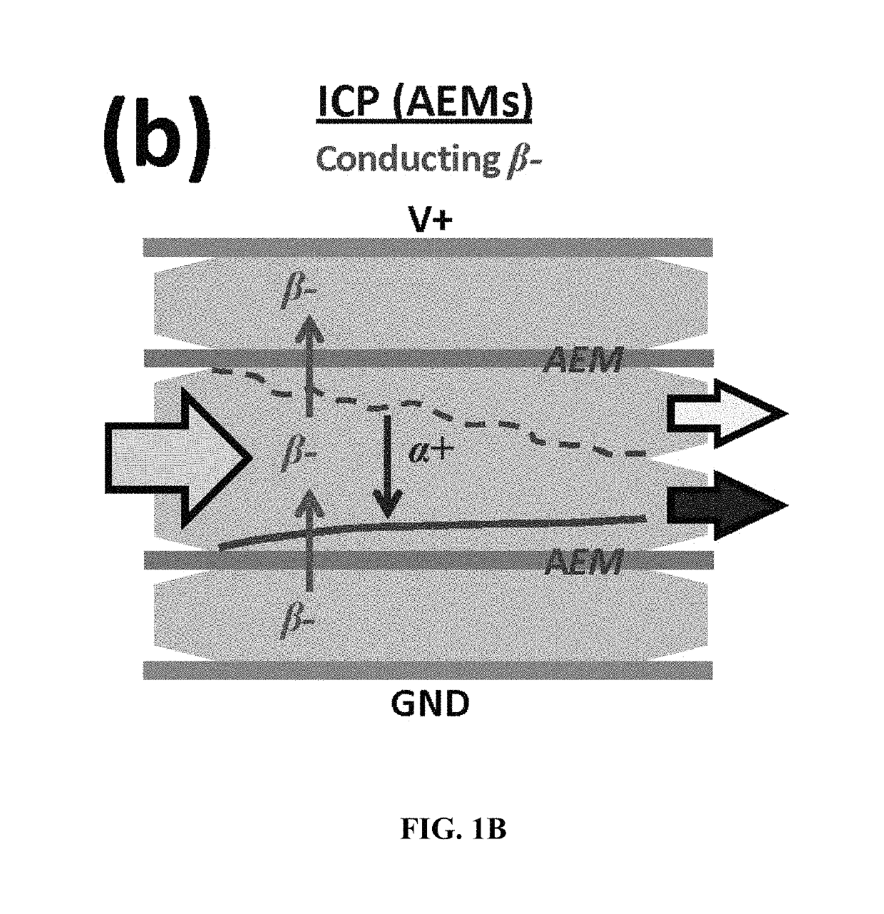
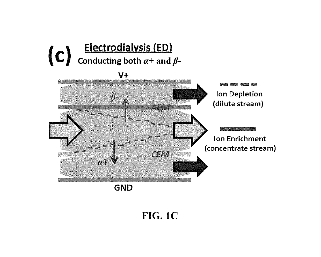
A water stream is passed between two juxtaposed similar ion exchange membranes (AEMs or CEMs), forming an ion depletion and ion enrichment zones when an electric field is applied. As cations are selectively transferred through the CEMs, for example, anions are relocated in order to achieve electro-neutrality, resulting in the concentration drop (increase) in ion depletion (enrichment) zone. Trifurcation of the output channel allows collection of concentrated, dilute and intermediate streams, with the intermediate stream serving as input to the next stage of a serialized implementation.

Description

RELATED APPLICATIONS[0001]This application claims the benefit of U.S. Provisional Application 62 / 067,501, filed Oct. 23, 2014. The entire teaching of the above application is incorporated herein by reference.GOVERNMENT SUPPORT[0002]This invention was made with Government support under Grant No. DE-AR0000294 awarded by the Department of Energy. The Government has certain rights in the invention.BACKGROUND OF THE INVENTION[0003]As water resources are rapidly being polluted, significant attention is now being paid to recovery of these waters through desalination and / or purification. In particular, with the adoption of horizontal drilling and hydraulic fracturing techniques to unlock the extensive natural energy resources from shale formations, issues regarding contaminated water from shale development are coming to the fore. Increasing development of shale gas sources has brought up an environmental issue concerning proper treatment of the often highly contaminated flowback or produced...

Claims


Application Information

Patent Timeline
Patent Type & Authority Patents(United States)
IPC IPC(8): C02F1/469C02F1/46B01D61/42C02F101/10C02F101/30C02F101/32C02F103/08
CPCC02F1/4695B01D61/42C02F1/4604C02F1/469C02F1/4698C02F2301/08C02F2101/30C02F2101/32C02F2103/08C02F2201/46115C02F2301/04C02F2101/10
Inventor KIM, BUMJOOHAN, JONGYOONKWAK, RHOKYUNAL-ANZI, BADER SHAFAQA
Owner MASSACHUSETTS INST OF TECH
Learn More