Eureka AIR delivers breakthrough ideas for toughest innovation challenges, trusted by R&D personnel around the world.

Synthesizer—power amplifier interface in a wireless circuit

Active Publication Date: 2019-04-09
SILICON LAB INC
View PDF2 Cites 5 Cited by
  • Summary
  • Abstract
  • Description
  • Claims
  • Application Information

AI Technical Summary

Benefits of technology

The invention is about a circuit that can correct the duty cycle of a power amplifier. The circuit uses feedback information from the power amplifier to adjust the duty cycle. It includes two paths, each with an inverter to receive a portion of the differential signal. These signals are then combined using a latch circuit to improve resistance to ground bounce and duty cycle variations. The result is a more stable and reliable power amplifier.

Problems solved by technology

Given the small size of the circuitry involved, many potential sources of interference may be present during wireless communications.
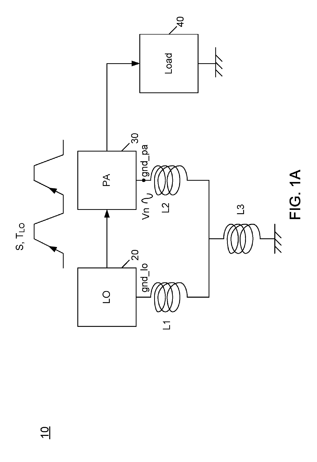
For example, when transmitting radio frequency (RF) signals via an associated power amplifier, high currents can cause ground bounce, which can impact duty cycle and thereby even-order harmonic emissions, spurs due to power supply rejection and so forth, and in certain cases adversely impact circuitry of the wireless transmitter itself due to stability issues.
And such solutions do not address adverse impacts on power amplifier stability due to inherent feedback through different ground domains itself.

Method used


Image

  • Synthesizer—power amplifier interface in a wireless circuit
  • Synthesizer—power amplifier interface in a wireless circuit
  • Synthesizer—power amplifier interface in a wireless circuit

Examples


Embodiment Construction

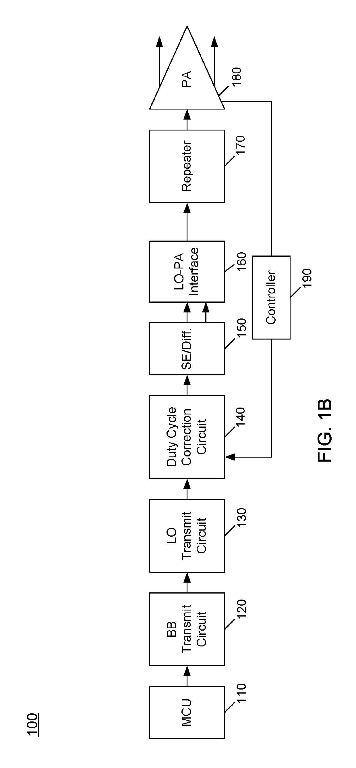
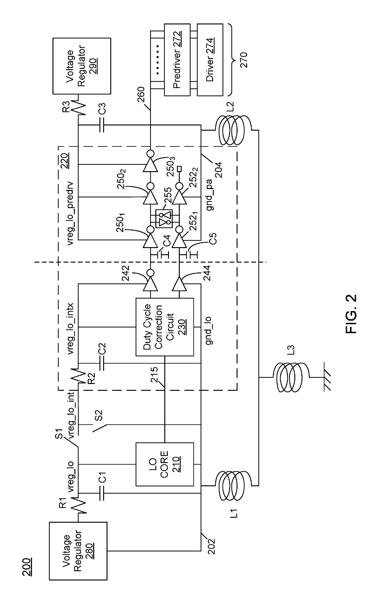
[0022]In various embodiments, circuitry may be adapted between a local oscillator (LO) portion of a transmitter circuit and a power amplifier (PA) of the transmitter circuit to enable duty cycle correction of the outgoing signal from the LO section. In addition, this circuitry may be used to convert signaling information from single-ended to differential form to allow further signal processing to be performed differentially, and thereafter to re-convert the signaling information back to single-ended form for communication to the power amplifier itself. In this way, reduced power consumption is realized, while at the same time providing for better signal performance, reducing distortions caused by various harmonics resulting from so-called ground bounce. This ground bounce may be caused by the power amplifier. And as a result, external filtering circuitry otherwise needed to filter signal information can be reduced or avoided, reducing cost and size of a given solution, by reducing o...


PUM


Abstract

In an embodiment, an apparatus includes: a transmit circuit to upconvert a baseband signal to a first differential radio frequency (RF) signal, the transmit circuit to convert the first differential RF signal to a first single-ended RF signal; a duty cycle correction circuit coupled to the transmit circuit to receive the first single-ended RF signal and compensate for a duty cycle variation in the first single-ended RF signal to output a duty cycle-corrected RF signal; a conversion circuit to convert the duty cycle-corrected RF signal to a second differential RF signal; and an interface circuit to transfer the second differential RF signal from a first ground domain to a second ground domain.

Description

CROSS-REFERENCED APPLICATIONS[0001]An application entitled “System and Method for Reducing Output Harmonics,” application Ser. No. 15 / 875,274, invented by Sherry X. Wu, Sriharsha Vasadi, Mustafa H. Koroglu, and Rangakrishnan Srinivasan, filed of even date herewith and assigned to the assignee hereof.BACKGROUND[0002]As technology advances, integrated circuits (ICs) are adapted into ever smaller packages and incorporated into many different kinds of devices. In many cases, so-called Internet of Things (IoT) devices may communicate using integrated wireless circuits. Given the small size of the circuitry involved, many potential sources of interference may be present during wireless communications. For example, when transmitting radio frequency (RF) signals via an associated power amplifier, high currents can cause ground bounce, which can impact duty cycle and thereby even-order harmonic emissions, spurs due to power supply rejection and so forth, and in certain cases adversely impact...

Claims


Application Information

Patent Timeline
IPC IPC(8): H04B1/04H03F3/45H03K3/017H03F1/32H03F3/195H03F3/213H03K3/0231
CPCH04B1/0475H03F3/195H03F3/213H03F3/45179H03K3/017H03F3/45636H03F1/3205H03K3/0231H03F2200/451H03F1/3211H03F2200/171H03K5/1565H04B1/0483H03K19/018521
Inventor SRINIVASAN, RANGAKRISHNANVASADI, SRIHARSHAWANG, ZHONGDAKOROGLU, MUSTAFA H.KHOURY, JOHN M.RAFI, ASLAMALI A.JOHNSON, MICHAEL S.BARALE, FRANCESCOWU, SHERRY XIAOHONG
Owner SILICON LAB INC
Why Eureka
Eureka Blog
Learn More