
Laser therapy system for noninvasive correction of the refractive system of the eye

a laser therapy and eye refractive technology, applied in the field of laser therapy system for noninvasive correction of the eye refractive system, can solve the problems of increasing the length of the eyeball, increasing the risk of infections, and refractive errors of the eye, so as to reduce the cytotoxic effect of uva light treatment, the growth of new collagen can be even more increased, and the effect of less uva light energy

Inactive Publication Date: 2019-04-16
TELESTO SP ZOO
View PDF3 Cites 4 Cited by
  • Summary
  • Abstract
  • Description
  • Claims
  • Application Information

AI Technical Summary

Benefits of technology

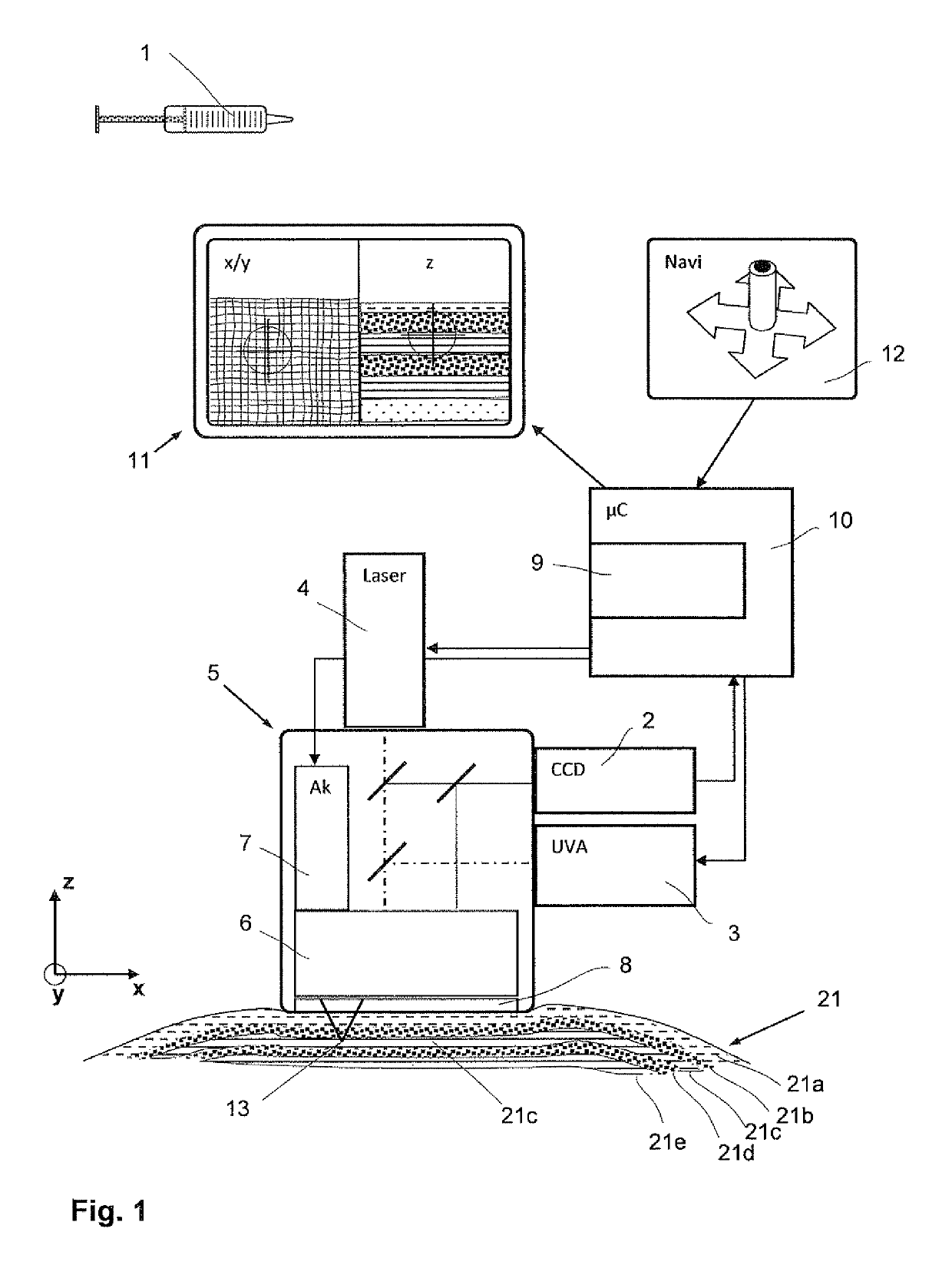
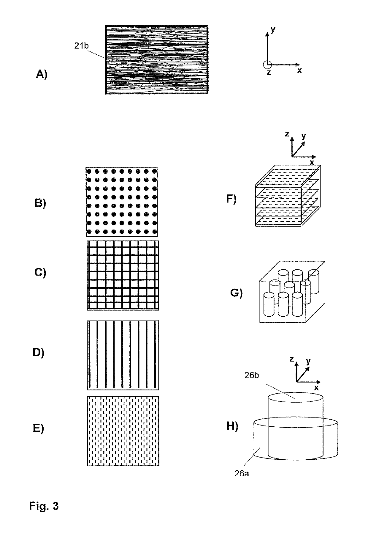
[0021]Advantageously the Laser therapy system comprises an imaging unit for 3D imaging of the cornea and / or sclera and an image processing unit which are adapted to recognize a current first collagen tissue structure and an orientation of the respective collagen fibers and collagen fiber bundles therein. Thus, by recognizing the orientation of the collagen fibers, the current first three-dimensional collagen structure of the collagen tissue is recognizable, wherein changes of said structure can be implemented in a determined way. Thus, the Laser therapy system allows not only a global change of the collagen tissue structure by a global growth of new crosslinks, but it allows also a determined growth of the new crosslinks, such that a determined microstructure can be built. Said microstructure can be built in a way, wherein the respective crosslinks can be induced in all three dimensions or directions, depending on the current first collagen tissue structure, existing forces such as the inner pressure of the eye and the definition of how the collagen tissue structure shall be formed. Preferably the Laser therapy system calculates the new shape of the eyeball in order to achieve a minimized refractive error of the eye and then calculates the new crosslinks necessary to achieve said new shape.
[0025]Thus the UVA light energy is preferably positioned stepwise or continuously along a plurality of paths describing a pattern as a dot matrix or a lined matrix in different possible ways and matrix forms, wherein the matrix is adapted to the orientation of the collagen fibers. Thus the matrix can be applied in a same plane as the collagen fibers or in a plane perpendicular thereto or in a volume with a direction aligned with or perpendicular to the collagen fibers. The crosslinks can be grown in a structure exactly adapted to the current first collagen tissue structure, to forces therein and to a new desired shape of the eyeball. It is obvious for a person skilled in the art that the desired shape is achievable with less UVA light energy compared with a less precise application of a different UVA light energy. A cytotoxic effect of the UVA light treatment is obviously reduced.
[0026]Using the photosensitizer as an agent for the skin and matching it with UVA light, said growth of the new collagen can be even more increased, or the UVA light energy can be decreased, respectively.
[0027]Preferably the Laser therapy system comprises also a second light source being a Laser, to be able to cut certain trenches or to apply a kind of a Laser Needling treatment in the sclera. The Laser Needling treatment induces a growth of new collagen. The Laser Needling is another advantageous treatment for an additional rejuvenation and strengthening of the skin and for a reshaping of the eyeball. As the Laser Needling treatment is preferably achievable with the same Laser therapy system as for the UVA light treatment, the patient does not have to be moved or readjusted from the UVA light treatment system to the Laser Needling system, such that no unnecessary time is lost and the same man-machine interface can be used by the surgeon. No adaptation effort of the user to another device has to be invested. Also, most of the components therein can be reused as the imaging unit, preferably the image processing unit, the optical system and the processing and control unit which are high-tech equipment and very expensive. A combination of the two different treatment technologies and methods with a same treatment objective is a good supplement and completion to correct the refractive system of the eye.
[0029]With regard to the image processing unit, the UVA light treatment can be applied in a more automatically controlled way and in a manner of micro-treatment which would not be possible by traditional manual treatment practices in a reasonable treatment time. Thus the treatment time can also be reduced in relation to the traditional manual treatment practices, reducing as well the treatment cost.

Problems solved by technology

With increasing age of a person refractive errors of the eye occur and are caused substantially by degradation of the eye tissue and in particular of the sclera and cornea.
Myopia is one of the most common new defective visions because of an increasing tallness of mankind resulting in an increasing length of the eyeball.
However this increases the risk of infections.
However the process takes only an ablation of cornea tissue into account and not a growth of new tissue.
However, the light energy is spread and not minimized for a desired growth of the new collagen cross-links.
However, the light energy is still spread and not minimized and controlled locally according to an orientation of the existing collagen fibers or fiber bundles.
However, the induction of the new crosslinks within the collagen tissue by the UVA light must also be seen in view of a toxic effect on the skin as well.

Method used


Image

  • Laser therapy system for noninvasive correction of the refractive system of the eye
  • Laser therapy system for noninvasive correction of the refractive system of the eye
  • Laser therapy system for noninvasive correction of the refractive system of the eye

Examples


Embodiment Construction

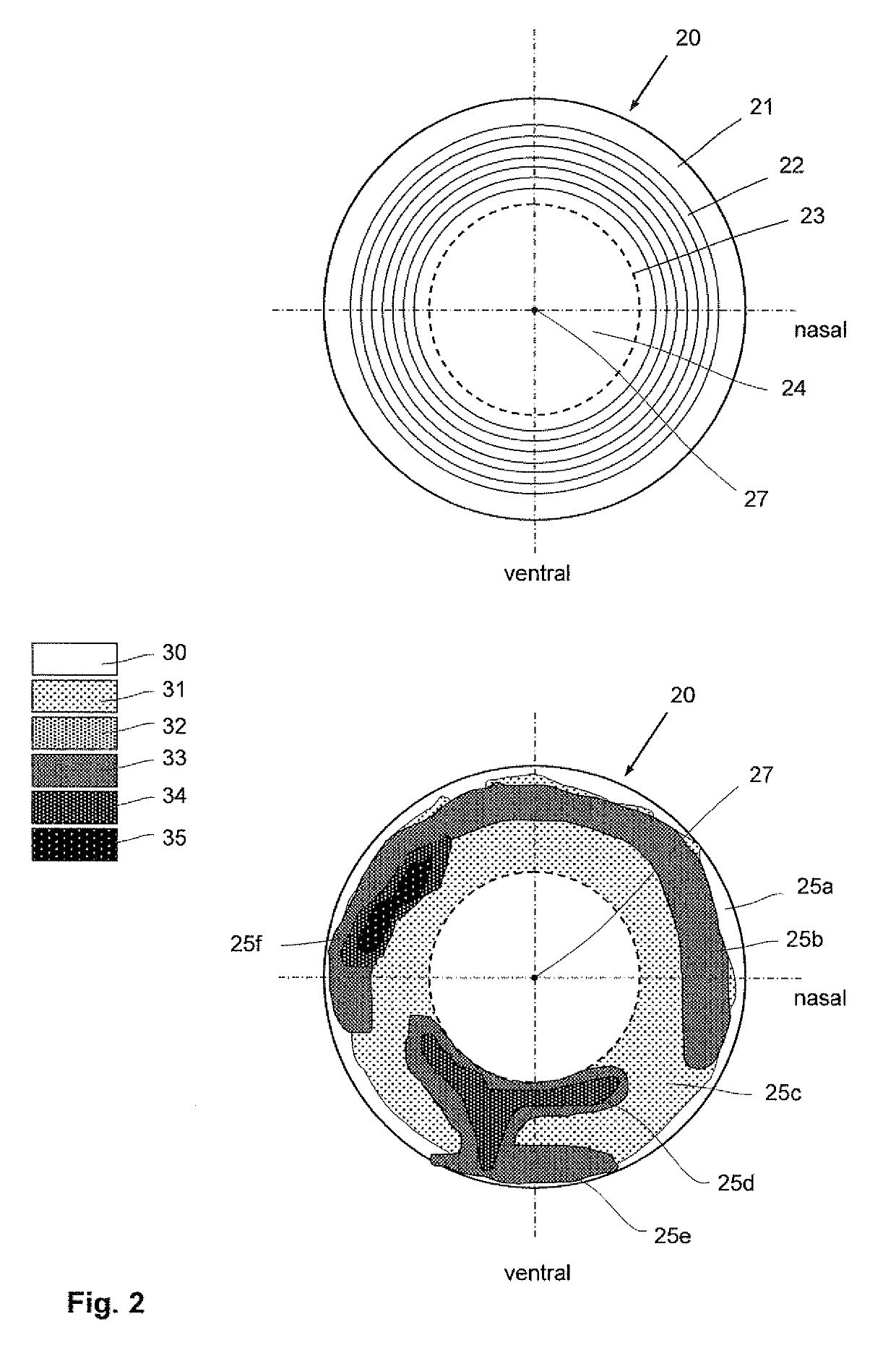
[0041]FIG. 1 shows a schematic diagram of the laser therapy system for an eye treatment and in particular for a treatment of the sclera 21 and / or cornea 24 of a living eye 20 according to a preferred embodiment of the invention. For the sake of clarity the terms “sclera”21 and / or “cornea”24 generally also stand for a part of said sclera and / or cornea. For the sake of brevity the sclera 21 and / or cornea 24 are also simply called skin in the following.

[0042]According to the invention, the Laser therapy system comprises a dispenser 1 such as a syringe, for example, containing an agent for an application on the skin, wherein the agent contains a photosensitizer for mediating a collagen and elastin crosslinking in a targeted manner during an UVA light irradiation. For the sake of brevity the word collagen preferably comprises also elastin. Generally, the word collagen also stands for a tissue or tissue structure of collagen fibers, wherein a plurality of collagen fibers connected with ea...


PUM


Abstract

The present invention refers to a Laser therapy system and a method for a treatment of a cornea and / or sclera of an eye to correct its refractive system, comprising:a dispenser for a photosensitizer agent;a 3D imaging unit;an image processing unit adapted to recognize a first collagen tissue structure and a first orientation of respective collagen fibers therein;a UVA light source adapted to a crosslinking within the collagen tissue structure;an optical system for deflecting and focusing the UVA light on a focus point behind an aperture within the imaging volume; anda processing and control unit adapted to receive data relating to a refractive error of the eye, to determine a second collagen tissue structure with new corrective collagen crosslinks, such as to achieve a minimized refractive error of the eye and a UVA light energy to induce the new corrective collagen crosslinks.

Description

[0001]The present invention refers to a Laser therapy system and a method for a noninvasive correction of the refractive system of an eye, comprising a 3D imaging unit for imaging a collagen tissue structure of the cornea and / or sclera, a UVA light source with an optical deflection and focusing system and a processing and control unit to position a focus point of the UVA light precisely in the cornea and / or sclera.BACKGROUND OF THE INVENTION[0002]The cornea and sclera make up the outer tunic of the eye. Each is a connective tissue containing collagen fibrils embedded in a proteoglycan-rich extrafibrillar matrix, wherein the cornea is uniquely transparent and the sclera is totally opaque. Both tissues require strength to maintain the excess pressure within the eye and to resist external knocks and forces applied by extraocular muscles during eye movement. The mechanical strength is provided by deposition of collagen in a lamellar structure, wherein the lamellae run parallel to the su...

Claims


Application Information

Patent Timeline
Patent Type & Authority Patents(United States)
IPC IPC(8): A61F9/008A61N5/06A61F9/007
CPCA61F9/00804A61F9/008A61F9/0079A61N5/062A61N2005/0661A61F2009/00853A61F2009/00865A61F2009/00872A61F2009/00851
Inventor DEPFENHART, MARKUS
Owner TELESTO SP ZOO
Learn More