
Homogeneous charge compression ignition engine

a charge compression and ignition engine technology, applied in the direction of machines/engines, mechanical equipment, non-fuel substance addition to fuel, etc., can solve the problems of large combustion noise, adversely affecting the reliability of the engine, and sudden combustion, and achieve the effect of suppressing the increase in the cylinder pressur

Inactive Publication Date: 2019-04-16
MAZDA MOTOR CORP
View PDF21 Cites 0 Cited by
  • Summary
  • Abstract
  • Description
  • Claims
  • Application Information

AI Technical Summary

Benefits of technology

The patent aims to create a homogeneous charge compression ignition engine that can maintain a good output torque without increasing the pressure in the cylinder.

Problems solved by technology

As a result, in a high load range of the engine, a sufficient amount of EGR gas may not be introduced into the cylinder, which may cause self-ignition too early or may cause steep combustion.
However, the aforementioned configuration may excessively increase an inner pressure of the cylinder (a cylinder pressure) during combustion, and large noise may be generated, which may adversely affect reliability of the engine.
However, unless an injection period is provided in such a manner that water exists at an appropriate timing during combustion, large combustion noise may be generated by a rapid increase in the cylinder pressure after combustion starts, for instance.
This may lower the commercial value of the engine.

Method used


Image

  • Homogeneous charge compression ignition engine
  • Homogeneous charge compression ignition engine
  • Homogeneous charge compression ignition engine

Examples


first embodiment

[0018](1) First Embodiment

[0019](i) Overall Configuration of Engine

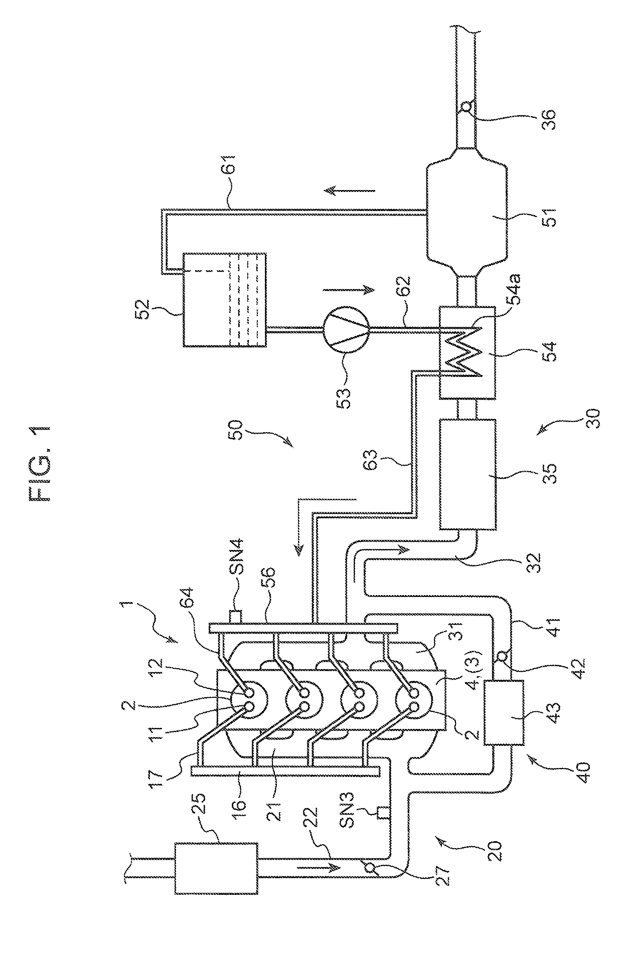
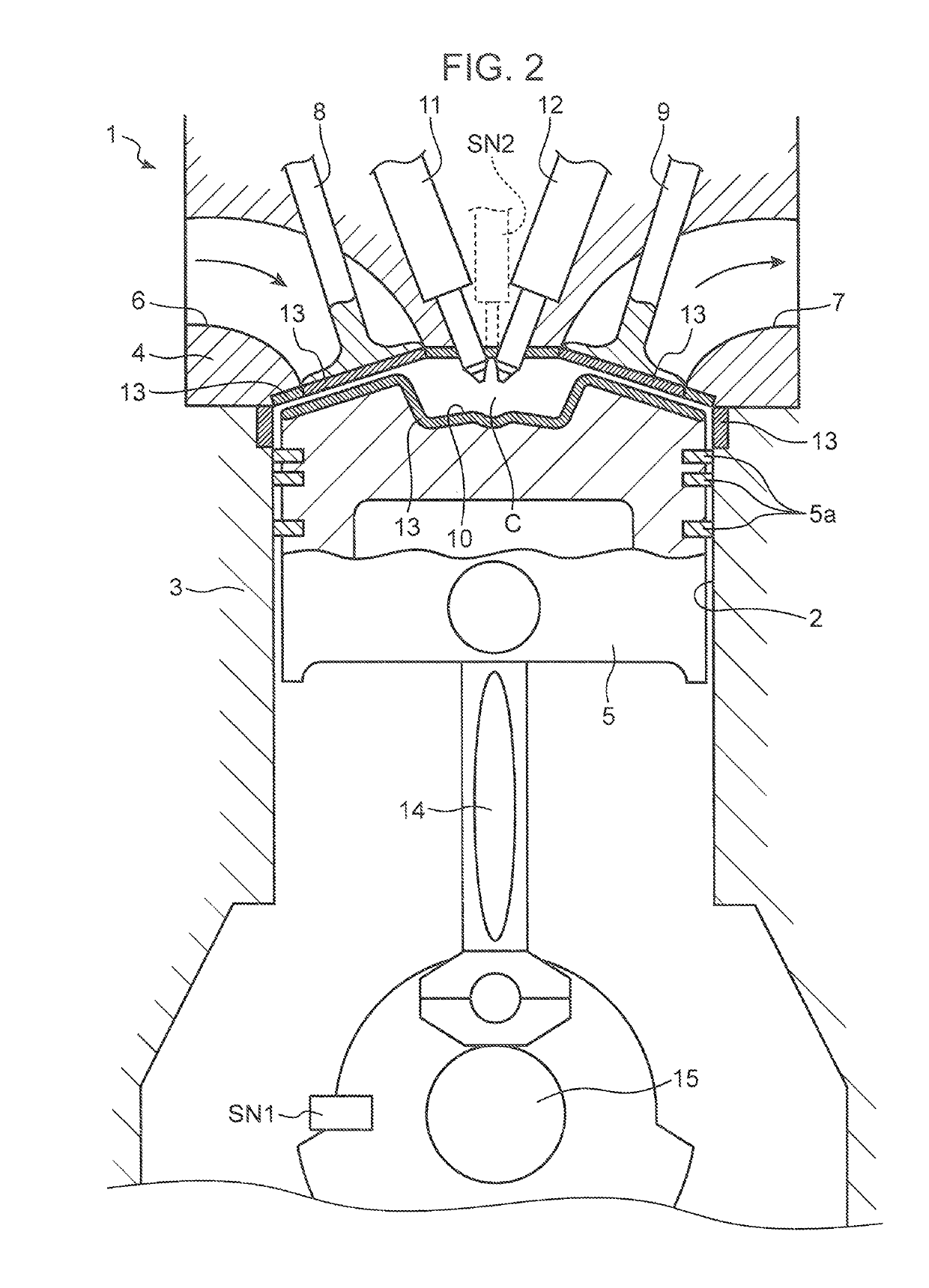
[0020]FIG. 1 and FIG. 2 are diagrams illustrating a homogeneous charge compression ignition engine according to the first embodiment of the present invention. The engine illustrated in FIG. 1 and FIG. 2 is a 4-cycle gasoline engine mounted in a vehicle as a power source for traveling. The engine includes an in-line multi-cylinder engine body 1 having four cylinders 2 arranged in a row, an intake passage 20 for passing intake air to be introduced to the engine body 1, an exhaust passage 30 for passing exhaust gas discharged from the engine body 1, an EGR device 40 for returning a part of exhaust gas passing through the exhaust passage 30 to the intake passage 20, and a water supply system 50 for supplying water extracted from exhaust gas passing through the exhaust passage 30 to each cylinder 2 of the engine body 1. The water supply device 50 corresponds to a critical water generation device in the claims.

[0021]As ill...

second embodiment

[0106](2) Second Embodiment

[0107]In the first embodiment, during an operation in the first operating range A1 on the high load side, two-times water injections (first water injection W1 and second water injection W2) are performed individually within a cycle in a state that a non injection period is provided between the two-times water injections. Water injection in the first operating range A1 may be a single continued injection. An example of the aforementioned configuration is described in the second embodiment as follows. In the second embodiment, the configuration other than the control relating to water injection is basically the same as in the first embodiment. Therefore, in the following, only the control relating to water injection is described.

[0108]FIG. 8 and FIG. 9 are diagrams illustrating a control example in the first operating range A1 to be employed in the second embodiment. FIG. 8 and FIG. 9 respectively correspond to FIG. 6 and FIG. 7 of the first embodiment. In t...


PUM


Abstract

A homogeneous charge compression ignition engine includes a cylinder configured to accommodate a piston to be reciprocally movable, a fuel injection valve configured to inject fuel into the cylinder, a water injection valve configured to inject water into the cylinder, a fuel injection control module configured to inject fuel from the fuel injection valve into the cylinder at such a timing that a mixture of fuel and air is self-ignited in a latter stage of a compression stroke or in an initial stage of an expansion stroke, and a water injection control module configured to perform at least a basic water injection of injecting water from the water injection valve into the cylinder during a predetermined period, which starts concurrently with or after start of combustion by the self-ignition and which overlaps a combustion period.

Description

TECHNICAL FIELD[0001]The present invention relates to a homogeneous charge compression ignition engine configured to combust fuel by self-ignition while mixing fuel injected into a cylinder with air.BACKGROUND ART[0002]As an example of the aforementioned engine, there is known an engine disclosed in Japanese Unexamined Patent Publication No. 2009-209809. In the engine disclosed in Japanese Unexamined Patent Publication No. 2009-209809, during an operation in a predetermined premixed combustion range, control such that a part of exhaust gas discharged to an exhaust passage is introduced into a cylinder as EGR gas, and fuel is injected into the cylinder at a timing earlier than the compression top dead center is performed. In this way, injecting fuel into a cylinder where EGR gas as inert gas exists makes it possible to cause self-ignition of injected fuel after a predetermined ignition delay, whereby appropriate combustion with a less amount of NOx or soot is performed.[0003]In a cas...

Claims


Application Information

Patent Timeline
Patent Type & Authority Patents(United States)
IPC IPC(8): F02M25/022F02B47/02F02B9/02F02M25/03
CPCF02M25/0227F02B9/02F02M25/03F02B47/02Y02T10/121Y02T10/12
Inventor NARAHARA, KAZUAKINOU, YOSHIHISAFUJIMOTO, MASAHIKOARAKI, KEIJI
Owner MAZDA MOTOR CORP
Learn More