Geothermal power plant

a geothermal power plant and power generation technology, applied in geothermal energy generation, directional drilling, lighting and heating apparatus, etc., can solve the problems of difficult control of fracturing process, difficult control of water flow in heat exchanger, difficult control of water flow, etc., to reduce drilling cost and risk, cost reduction, and optimize energy output

Active Publication Date: 2019-04-16
GEOVARME AS
View PDF13 Cites 8 Cited by
  • Summary
  • Abstract
  • Description
  • Claims
  • Application Information

AI Technical Summary

Benefits of technology

[0006]It is an object of the present invention to provide a geothermal energy plant design combining the supply and return holes and thereby allowing a significant reduction of drilling cost and risk related to plant manufacture. Further cost reduction is allowed by the invention as drilling patterns are optimized with respect to energy output versus drilling costs. Two complementary concepts are presented. In rock formations with high temperature gradients a design with essentially “vertical” production holes can be advantageous due to the simplicity with which the plant can be established. In rock with relatively low temperature gradients energy output is optimized and total cost is reduced by making production holes essentially “horizontal”. However, the two concepts, or some combination of the two, are applicable for both low and high temperature gradients, and the design will be chosen based on the actual application and operating conditions of the plant. A method for establishing the presented design of a geothermal energy plant is also claimed.

Problems solved by technology

While drilling costs can be lower than for many alternatives, there are several practical challenges related to the proposed methods.
First, it is difficult to control the fracturing process and thereby the establishment of the heat exchanger in the geological formation.
Second, water flow in the heat exchanger is difficult to control and optimize as the water will tend to follow the path of least hydraulic resistance and not the path for optimal heat production.
Thirdly, the fractured volume is difficult to maintain as the fractures may get clogged and cannot easily be re-opened.
Research and development of fractured rock designs has been pursued for half a century with limited practical success.
A large number of wells are needed to allow a reasonable large heat output, and supply and return holes widely separated would give a rather impractical plant design.
The challenge for all such solutions is to ensure sufficient heat transfer from the rock.
With significant cost of drilling it would be impractical to establish multiple injection and return wells.
Supply and return holes are particularly expensive to drill and do not contribute much to heat production.

Method used


Image

  • Geothermal power plant
  • Geothermal power plant
  • Geothermal power plant

Examples


Embodiment Construction

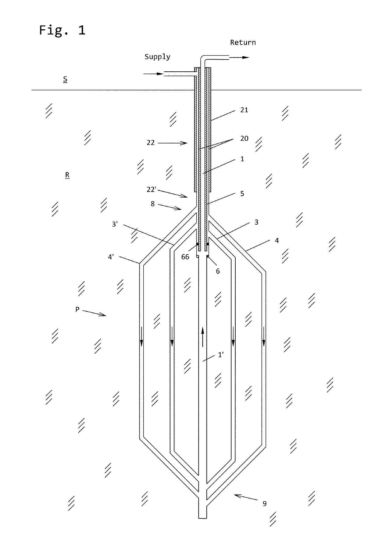
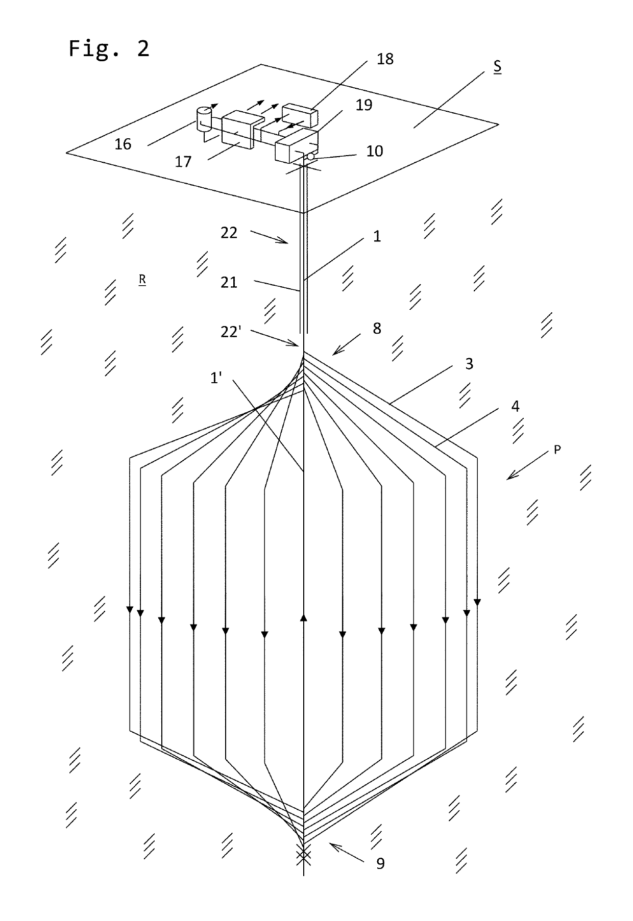
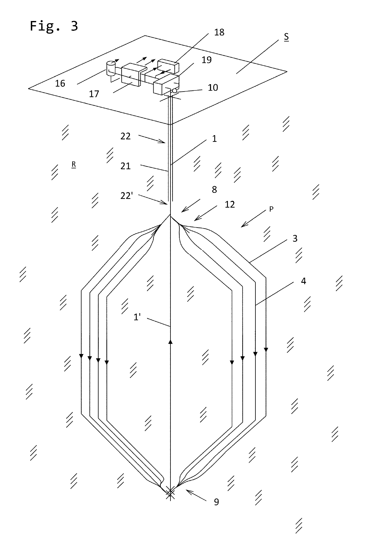
[0036]FIG. 26 illustrates the concept related to “horizontal” production holes, while FIG. 27 illustrates the concept related to “vertical” production holes. The main feature common to both concepts is the combined supply and return hole consisting of the borehole with an inner insulated pipe and a seal in the annular space separating the supply fluid flow from the return fluid flow. The insulated pipe can, for example, be a metal pipe with an outer layer of thermally insulating material or consist of only thermally insulating material. There exist various types of seals that can be used. The borehole is extended below the seal with the same or a smaller diameter hole forming a part of the return fluid flow. Casing in the upper part of the borehole is installed as required.

[0037]In FIG. 26 the production holes are drilled with an essential horizontal pattern near the bottom of the borehole giving the highest rock temperature and energy output per meter of production hole.

[0038]In FI...


PUM


Abstract

A plant for exploiting geothermal energy by circulating water or another fluid through a non-porous geological formation at a substantial depth below the earth surface, comprising multiple heat absorbing / production holes penetrating the said formation, with a total length of several kilometers and spaced more than 50 m apart. The production holes are connected to the surface by one single combined supply and return hole in which upward and downward flow is separated by a pipe comprising an insulating material and a seal. At the given positions of the common supply and return hole manifold zone designs connect the hole to the multiple production holes. The supply and return holes and production holes are closed circuits for transport of a fluid such as water through the said formation. A method for designing and establishing the plant is also disclosed.

Description

FIELD OF THE INVENTION[0001]The present invention relates to an energy plant for exploiting geothermal energy by circulating a fluid such as water through a geological formation. The invention also relates to a method for establishing a geothermal energy plant.BACKGROUND[0002]Even in regions of the world that are not geologically active, the vertical temperature gradient in the earth crust usually exceeds 20° C. / km. Hence at a depth of 5000 m, rock temperatures exceeding 100° C. are expected. There are large geographical variations. In some areas not considered geologically active, thermal gradients in the crust exceed the indicated number by a factor of two or more. Gradients lower than 20° C. / km appear to be uncommon. High gradients are typically experienced where insulating layers of rock are stacked on top of heat producing rock or intrusions of eruptive rock. Hot Dry Rock (HDR) is rock formations with low porosity and with no natural aquifers. In such rocks heat transfer takes ...

Claims


Application Information

Patent Timeline
Patent Type & Authority Patents(United States)
IPC IPC(8): E21B7/00F24T10/10E21B7/06
CPCF24T10/10E21B7/061E21B7/00Y02E10/12F24T10/30Y02E10/10
Inventor SONJU, OTTO KRISTIANHALMRAST, BJORNMOE, PER THOMAS
Owner GEOVARME AS
Why Eureka
Try Eureka