Imprint mold and imprint method
a technology of imprinting and molds, applied in the field of imprinting molds, can solve the problems of difficult reuse of damaged molds, increased mold manufacturing costs, and long time to complete, and achieve the effects of accurate detection of magnitude, control of pattern accuracy, and high accuracy
- Summary
- Abstract
- Description
- Claims
- Application Information
AI Technical Summary
Benefits of technology
Problems solved by technology
Method used
Image
Examples
example 1
[0177]
[0178]A quartz glass substrate (152 mm×152 mm, thickness 6.35 mm) was prepared as a flat plate-like base, and an uneven structure area of 25 mm×30 mm was set at the center of a surface of the base.
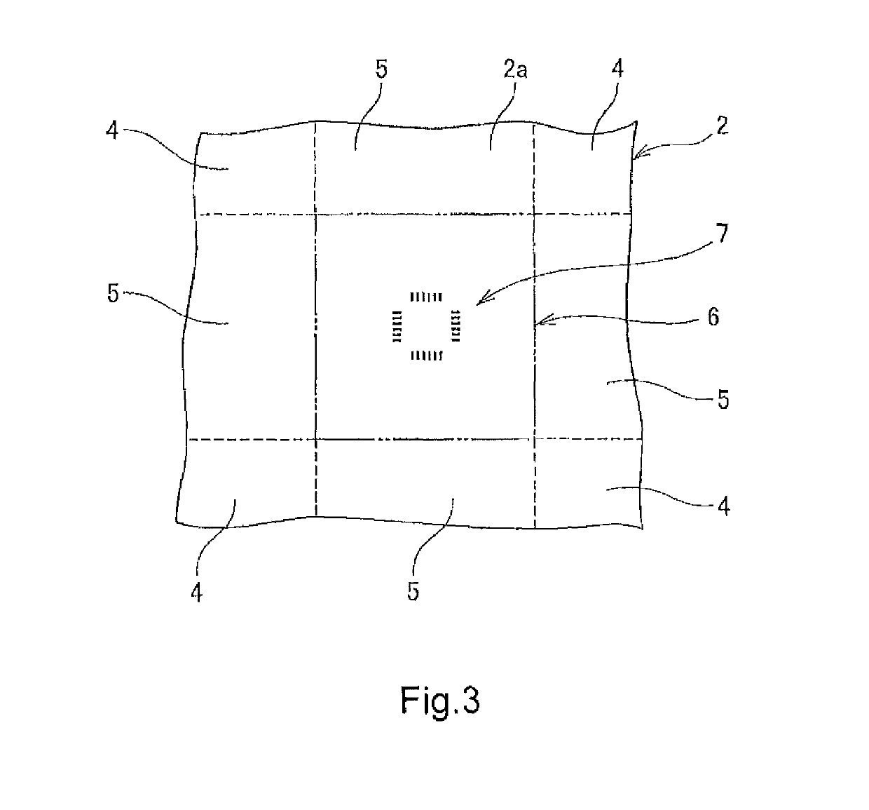
[0179]Next, a chromium thin film was formed on the surface of the base by a sputtering method. Then, an electron beam positive resist was applied onto the chromium thin film by a spin coating method. A desired resist pattern was formed on a hard mask material layer in the uneven structure area by performing electron beam drawing based on design coordinates on the application film and performing development. In the design coordinates, rectangular main pattern areas (1530 μm×1320 μm) were set so as to form a grid, and non-main pattern areas were set so as to form a lattice in gap portions of the individual main pattern areas (see FIG. 2). Square measurement areas (100 μm×100 μm) were set at 352 positions in the intersection portions of the non-main pattern areas. Further, in each measu...
example 2
[0190]
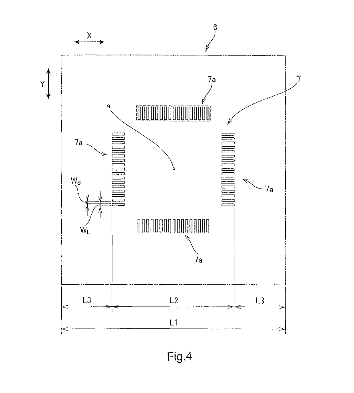
[0191]Four non-drawing areas each having a rectangular plan view shape (1 μm×8 μm) were set so as to be positioned at individual sides of a 12-μm square in each measurement area of the design coordinates of the electron beam drawing. In addition, along long sides of the four rectangular non-drawing areas, pixel areas in the line / space shape (line: 0.2 μm, space: 0.2 μm) that were disposed such that the longitudinal direction of each line was orthogonal to the long side, and had the length of each line of 1 μm were set. Further, a drawing area in the line / space shape (line: 0.2 μm, space: 0.2 μm) that was disposed such that the longitudinal direction of each line matched the Y direction (see FIG. 12) was set in the measurement area other than the pixel area and the non-drawing areas described above. The master mold was fabricated in the same manner as in Example 1 except that each measurement area was set in the above manner.
[0192]The master mold included, in each measurement a...
example 3
[0205]
[0206]As a flat plate-like base, a quartz glass substrate (152 mm×152 mm, thickness 6.35 mm) was prepared, and an uneven structure area of 25 mm×30 mm was set at the center of a surface of the base.
[0207]Next, a chromium thin film was formed on the surface of the base by the sputtering method. Then, an electron beam-sensitive positive resist was applied onto the chromium thin film by the spin coating method. A desired resist pattern was formed on a hard mask material layer in the uneven structure area by performing electron beam drawing based on design coordinates on the application film and performing development. In the design coordinates, rectangular main pattern areas (1530 μm×1320 μm) were set so as to form a grid, and non-main pattern areas were set so as to form a lattice in gap portions of the individual main pattern areas. Square measurement areas (100 μm×100 μm) were set at 352 positions in the intersection portions of the non-main pattern areas (see FIG. 17). Furthe...
PUM
| Property | Measurement | Unit |
|---|---|---|
| constant angle | aaaaa | aaaaa |
| constant angle | aaaaa | aaaaa |
| length L2 | aaaaa | aaaaa |
Abstract
Description
Claims
Application Information
 - R&D
- Intellectual Property
- Life Sciences
- Materials
- Tech Scout
- Unparalleled Data Quality
- Higher Quality Content
- 60% Fewer Hallucinations
Browse by: Latest US Patents, China's latest patents, Technical Efficacy Thesaurus, Application Domain, Technology Topic, Popular Technical Reports.
© 2025 PatSnap. All rights reserved.Legal|Privacy policy|Modern Slavery Act Transparency Statement|Sitemap|About US| Contact US: help@patsnap.com


