Multiphase voltage converter with coupled inductors of reduced winding loss and core loss

a voltage converter and inductor technology, applied in the direction of dc-dc conversion, power conversion systems, instruments, etc., can solve the problems of adversely affecting the energy conversion efficiency, increasing the power loss of the magnetic core, and increasing so as to improve the transient response of the converter and reduce the resistance of the inductor winding. , the effect of low conductor resistan

Active Publication Date: 2019-04-23
HUANG WENKANG +1
View PDF10 Cites 0 Cited by
  • Summary
  • Abstract
  • Description
  • Claims
  • Application Information

AI Technical Summary

Benefits of technology

[0006]In a two-phase switching converter, conductors of the coupled inductors are straight and non-looping. Top and bottom switches of the first phase are on one side of the magnetic core, and top and bottom switches of the second phase is on the other side of the magnetic core. The current of the two inductors are in opposite direction. With the unique structure of lateral magnetic core and non-looping conductors, the coupled inductors will be inversely coupled, and will have a low conductor resistance. The inverse coupling improves transient response of the converters. The relatively low resistance in inductor windings and relatively small core volume in magnetic core of the coupled inductors reduce converter power loss and, therefore, increase energy conversion efficiency.
[0012]The converter can be a single-phase converter, in which case no coupling is required, but the non-looping conductor in the inductor reduces the inductor winding resistance and improves the energy conversion efficiency.

Problems solved by technology

However, the extra conductor windings required for inductors with inverse coupling increases resistance of the inductors, which adversely affects the energy conversion efficiency.
In another prior art, the woven topology of inductor core required for inductors with inverse coupling increases volume of the magnetic core, which increases power loss of magnetic core and adversely affects the energy conversion efficiency.

Method used


Image

  • Multiphase voltage converter with coupled inductors of reduced winding loss and core loss
  • Multiphase voltage converter with coupled inductors of reduced winding loss and core loss
  • Multiphase voltage converter with coupled inductors of reduced winding loss and core loss

Examples


Embodiment Construction

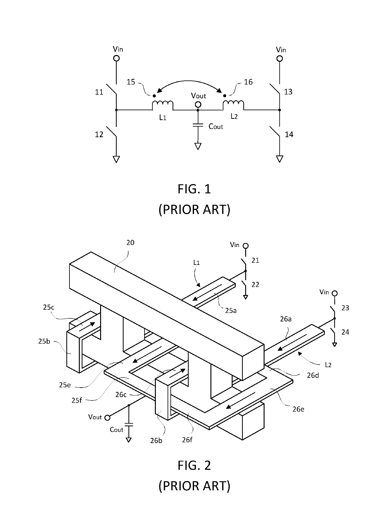
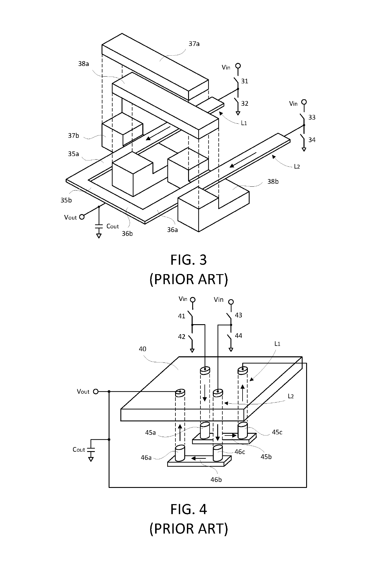
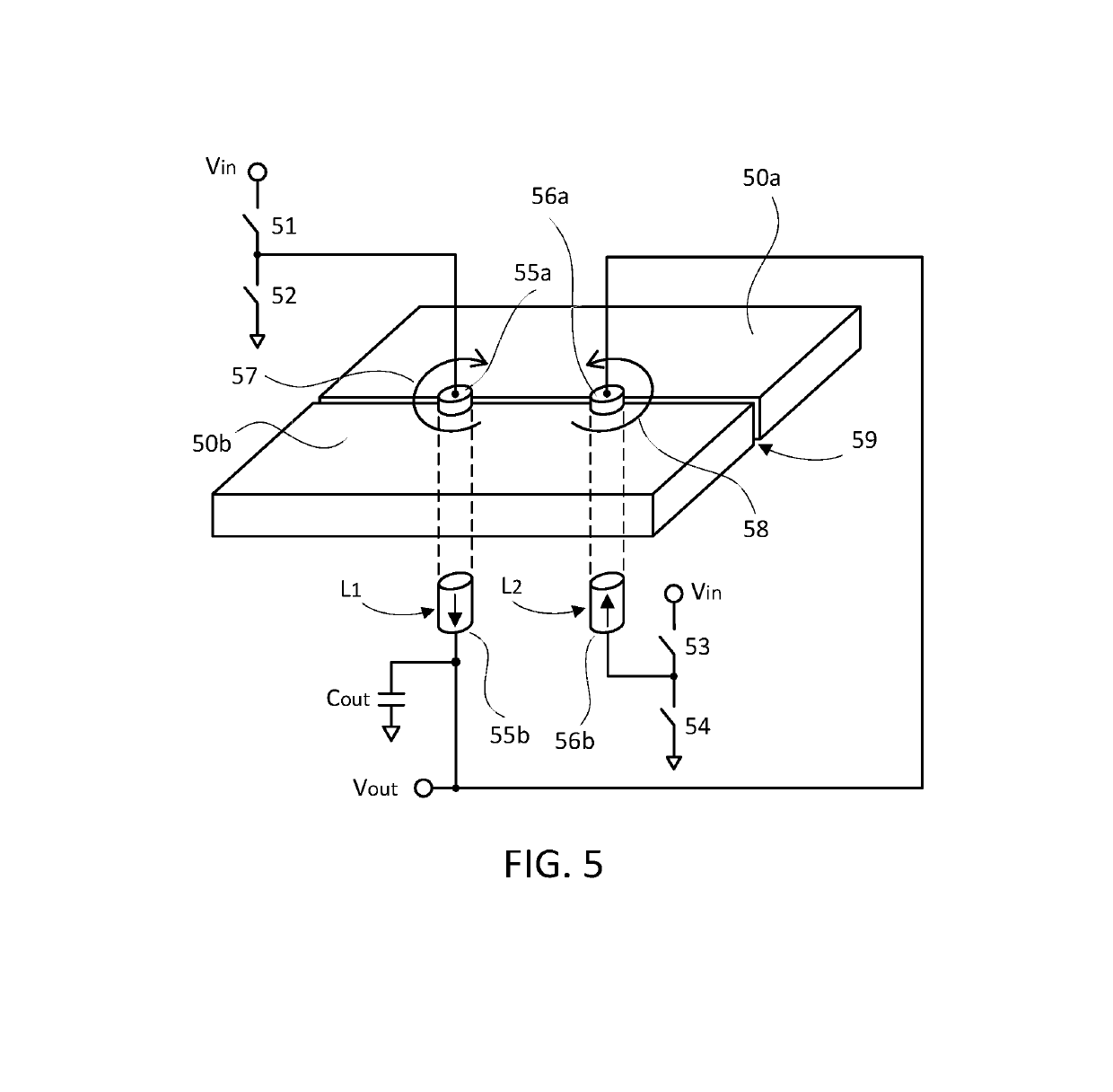
[0027]The present invention provides multiphase voltage converters having coupled inductors with reduced winding resistance and magnetic core volume. In a conventional, prior art multiphase converter with inversely coupled inductors (i.e. with a negative coupling coefficient), the inductors comprise long electrical conductors wound around a magnetic core. In another prior art multiphase converter with inversely coupled inductors, the inductors comprise long magnetic cores woven around the electrical conductors. In the present invention, the conductors of the coupled inductors are non-looping, and by comparison, the conductors are much shorter. The lateral magnetic core further decreases the length of the conductors. The combination of the non-looping conductors and the lateral magnetic core reduces conductor resistance and magnetic core size. As a result, the inductor power losses are reduced and the conversion energy efficiency of the voltage converter is increased in the present i...


PUM

PropertyMeasurementUnit
frequenciesaaaaaaaaaa
voltageaaaaaaaaaa
permeabilityaaaaaaaaaa

Abstract

A multiphase switching DC-DC converter generates an output voltage from an input voltage. The converter includes multiphase coupled inductors having lateral magnetic core and non-looping conductors. The currents in conductors of the inductors flow in opposite directions, and therefore, the coupled inductors are inversely coupled and have a relatively low resistance and relatively small core volume. The reduced resistance of the inductor windings combined with smaller volume of magnetic core in the coupled inductors increases energy conversion efficiency and improves transient response of the converter. The coupled inductors can be employed in buck or boost or buck-boost converters, and they can also be used in buck or boost or buck-boost derived converters with isolation transformers.

Description

FIELD OF THE INVENTION[0001]The invention relates generally to multiphase switching DC-to-DC voltage converters such as buck or boost or buck-boost converters, and buck or boost or buck-boost derived converters with an isolation transformer.BACKGROUND OF THE INVENTION[0002]Buck converters are typically used to regulate the voltage of a DC power supply. A multiphase buck converter has several phases connected in parallel, with each phase having a top switch and a bottom switch connected to an inductor. Such multiphase buck converters are well known in the art and are commonly used for providing regulated DC power to loads that require higher current, fast transient response, and high conversion efficiency, such as microprocessors, computer memories, computer graphic processors, telecommunications electronics, and field-programmable gate array and other integrated circuits.[0003]The prior art has sought to increase conversion efficiency and improve transient response of a multiphase b...

Claims


Application Information

Patent Timeline
Patent Type & Authority Patents(United States)
IPC IPC(8): H02M3/158H01F27/24H01F27/28H01F27/40
CPCH02M3/1584H01F27/24H01F27/28H01F27/40
Inventor HUANG, WENKANGLEHMAN, BRADLEY M.
Owner HUANG WENKANG
Why Eureka
Try Eureka