Supercharge Your Innovation With Domain-Expert AI Agents!

Cryopump and method of operating the cryopump

a cryopump and cryoelectric technology, applied in the direction of positive displacement liquid engines, separation processes, lighting and heating apparatus, etc., can solve the problems of difficult to create such a temperature difference, temperature adjustment at the end of the cool-down takes a certain period of time, and the relative size of the temperature difference is required. to achieve the effect of shortening the cooling time of the cryopump

Active Publication Date: 2019-04-30
SUMITOMO HEAVY IND LTD
View PDF17 Cites 0 Cited by
  • Summary
  • Abstract
  • Description
  • Claims
  • Application Information

AI Technical Summary

Benefits of technology

This approach significantly shortens the cool-down time of the cryopump, reducing downtime by enabling faster temperature equilibration between the stages without requiring significant modifications to the refrigerator or compressor design.

Problems solved by technology

Although the cryopump is one of the major applications of a cryogenic refrigerator, it is different from other applications in that a relatively large temperature difference is required between a high-temperature stage and a low-temperature stage of the refrigerator.
However, when the cryopump is cooled, it is not easy to create such a temperature difference in a short period of time.
Such temperature adjustment in the end of the cool-down takes a certain period of time.
In particular, when a large temperature difference is required between the high-temperature stage and the low-temperature stage, the temperature adjustment takes a long period of time.

Method used


Image

  • Cryopump and method of operating the cryopump
  • Cryopump and method of operating the cryopump
  • Cryopump and method of operating the cryopump

Examples


Embodiment Construction

[0019]The invention will now be described by reference to the preferred embodiments. This does not intend to limit the scope of the present invention, but to exemplify the invention.

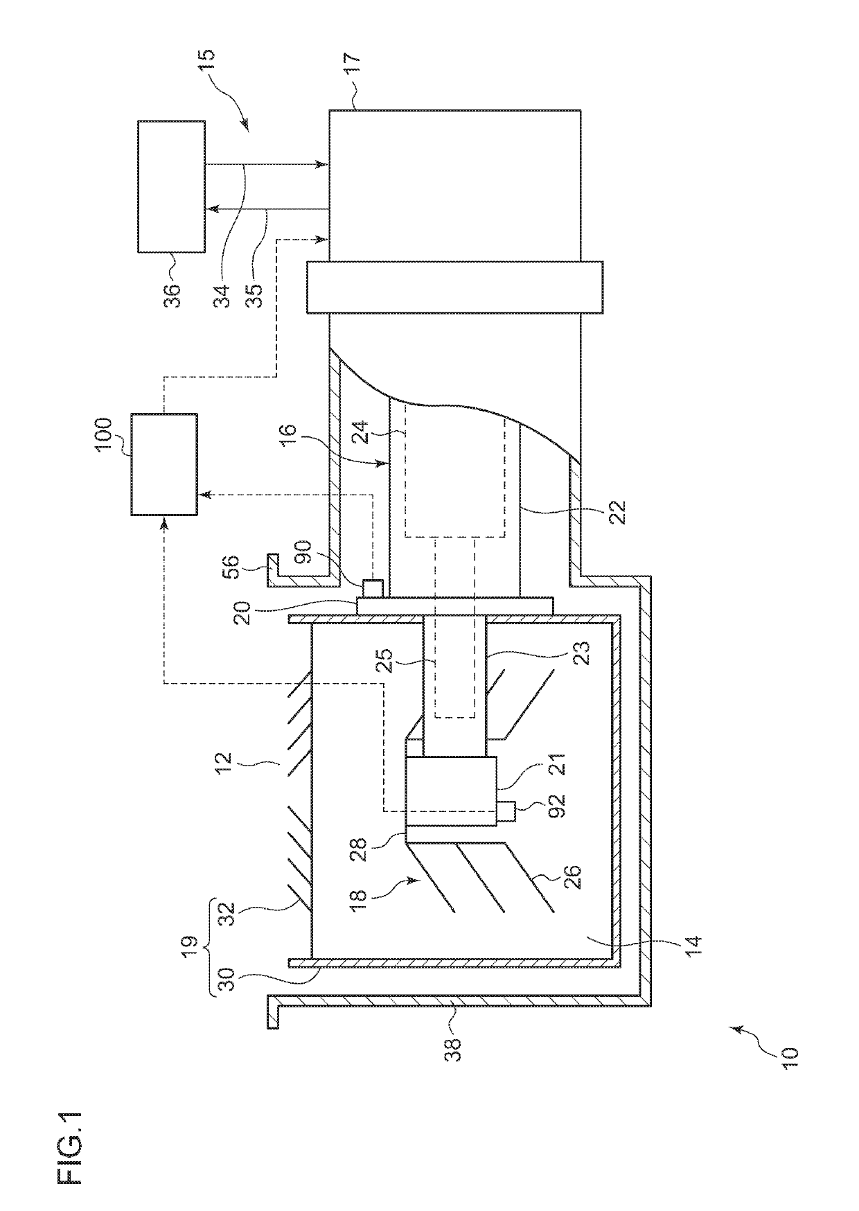
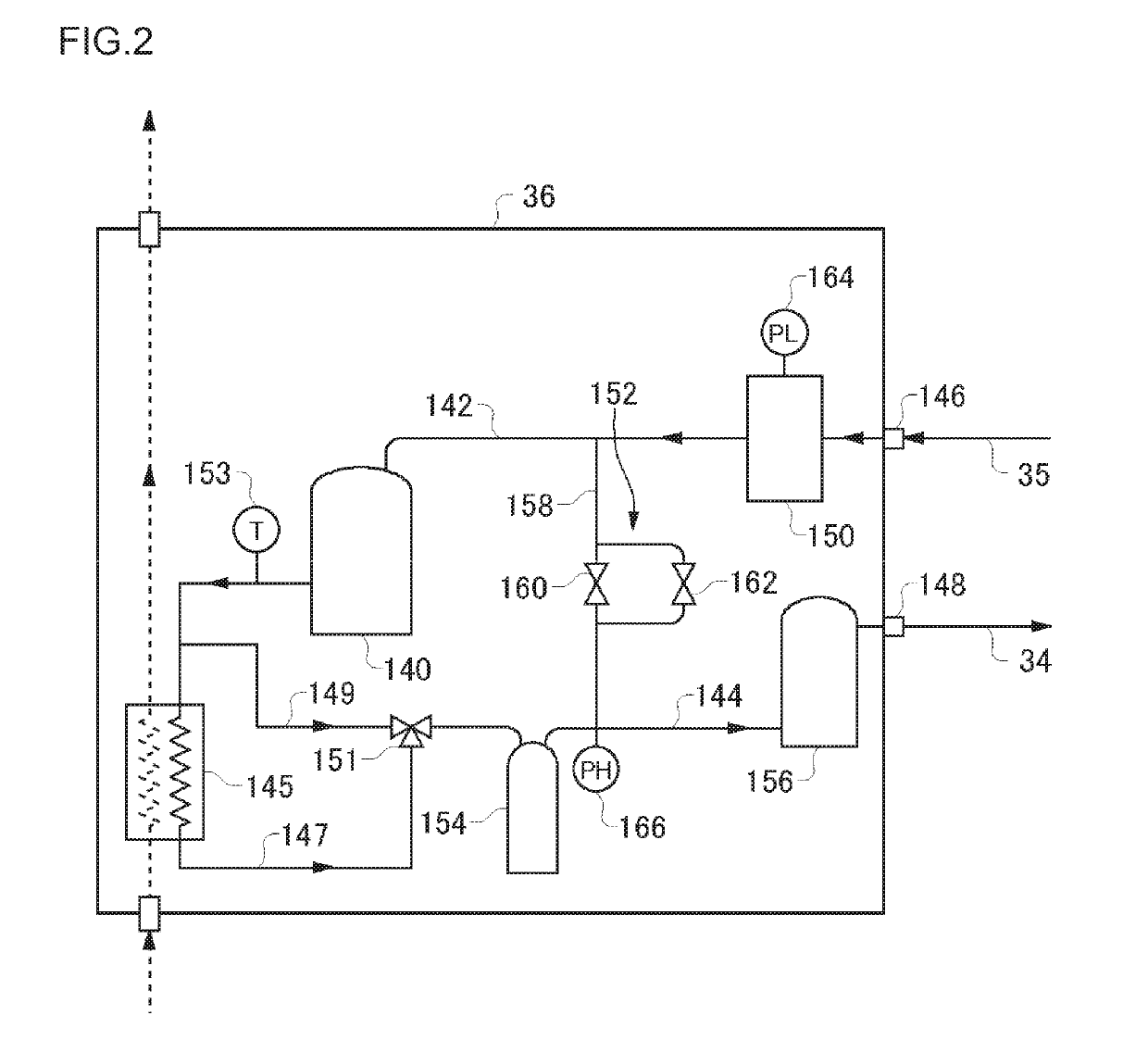
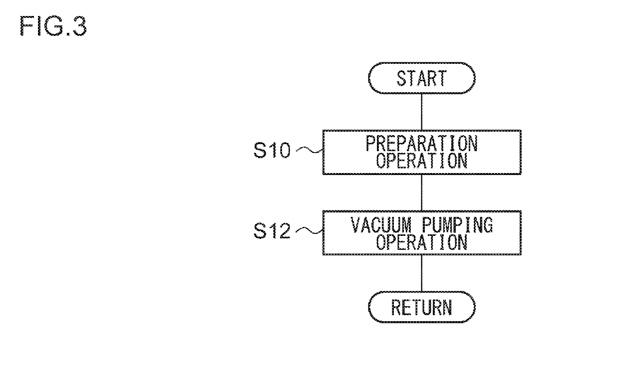
[0020]According to an embodiment of the present invention, a cooling relief effect (i.e., an effect that reduces a cooling capability) is selectively provided to a high-temperature stage during a cool-down operation while the cooling of a low-temperature stage continues at the normal level. This enables a larger difference in temperature to be generated rapidly between the high-temperature stage and the low-temperature stage. Accordingly, a temperature deviation of the low-temperature stage (or of the high-temperature stage) from its target temperature when the high-temperature stage (or the low-temperature stage) is finally cooled to its target temperature can be reduced. Therefore, a period of time required for the temperature adjustment in the end of cool-down can be shortened. As a result, a cool-dow...


PUM


Abstract

A method of operating a cryopump includes: cooling a cryopanel from an initial temperature higher than a cryogenic temperature for a vacuum pumping operation to the cryogenic temperature by using a refrigerator; and after the cooling, initiating the vacuum pumping operation, in which the cooling includes providing a cooling relief effect selectively to a high-temperature stage of the refrigerator.

Description

CROSS-REFERENCE TO RELATED APPLICATION[0001]This is a divisional of U.S. patent application Ser. No. 14 / 182,778 filed on Feb. 18, 2014, claiming priority to Japanese Patent Application No. 2013-028723 filed on Feb. 18, 2013, the contents of which are incorporated herein by reference in their entirety.BACKGROUND[0002]Technical Field[0003]The present invention relates to a cryopump and a method of operating the cryopump.[0004]Description of Related Art[0005]When a new cryopump is installed on site, the cryopump is cooled from a room temperature to a cryogenic temperature and a vacuum pumping operation is initiated. Further, the cryopump is a gas entrapment vacuum pump, as known, and hence regeneration is performed at a certain interval in order to discharge entrapped gas to the outside. Regeneration processing generally includes a temperature-raising step, a discharge step, and a cooling step. When the cooling step is terminated, the vacuum pumping operation of the cryopump is resumed...

Claims


Application Information

Patent Timeline
Patent Type & Authority Patents(United States)
IPC IPC(8): F04B37/08B01D8/00F04C18/02F25B9/14
CPCF04B37/08B01D8/00F04C18/0215F04B37/085F25B9/14
Inventor TAKAHASHI, KAKERU
Owner SUMITOMO HEAVY IND LTD
Features
  • R&D
  • Intellectual Property
  • Life Sciences
  • Materials
  • Tech Scout
  • Unparalleled Data Quality
  • Higher Quality Content
  • 60% Fewer Hallucinations
Learn More