Perforated drum of a compressor of an axial turbine engine

a technology of compressor and perforated drum, which is applied in the direction of engine fuction, leakage prevention, air transportation, etc., can solve the problems of loss of mixing, leakage around the rows of stator vanes, and affect thermodynamic behaviour

Active Publication Date: 2019-04-30
TECHSPACE AERO
View PDF14 Cites 0 Cited by
  • Summary
  • Abstract
  • Description
  • Claims
  • Application Information

AI Technical Summary

Benefits of technology

[0052]The arrangement of the intake orifices on the rotor offers more space. Since there are fewer constraints on the choice of diameter of the orifices, their number may be reduced. Fewer zones are affected. The cost of the corresponding rotor is then reduced. Savings are also achieved since simple piercings on the rotor have an effect. The effect on the forms and the methods of production of the other components of the turbine engine is limited or zero. The integration of the insert is also simplified.
[0053]Evacuation outside the rotor simplifies its operation and hence its design. Evacuation of leakages or secondary discharges towards the downstream side of the rotor does not disturb the flow in the turbine engine. The boundary layers are no longer adversely affected and adhere better to their wall. Maintenance is simplified since a single orifice through the wall is sufficient to manage the extraction. The break-up of the abradable layer is less disruptive since the orifices have a simple geometry. There is less risk of their becoming blocked, and less risk of blockage of the leakage escape circuit.

Problems solved by technology

In fact, on operation of the turbine engine, leakages pass around the rows of stator vanes.
These recirculations cause losses by mixing.
The thermodynamic behaviour is also affected, in particular due to the creation of entropy.
The vanes of a low-pressure compressor are generally fine, and consequently this solution is not satisfactory.
In addition, this configuration generates an additional cost for housing the cavities.

Method used


Image

  • Perforated drum of a compressor of an axial turbine engine
  • Perforated drum of a compressor of an axial turbine engine
  • Perforated drum of a compressor of an axial turbine engine

Examples


Embodiment Construction

[0016]The present application aims to solve at least one of the problems posed by the prior art. More precisely, the object of the present application is to simplify management of the recirculations in an axial turbine engine. The object of the present application is also to increase the capacity for intercepting recirculations.

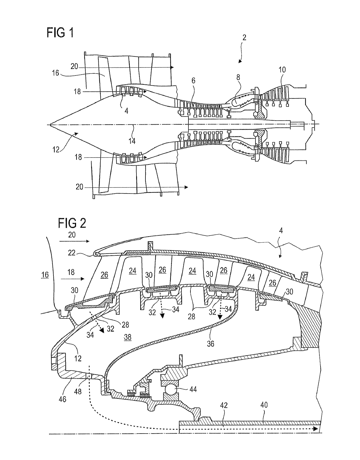
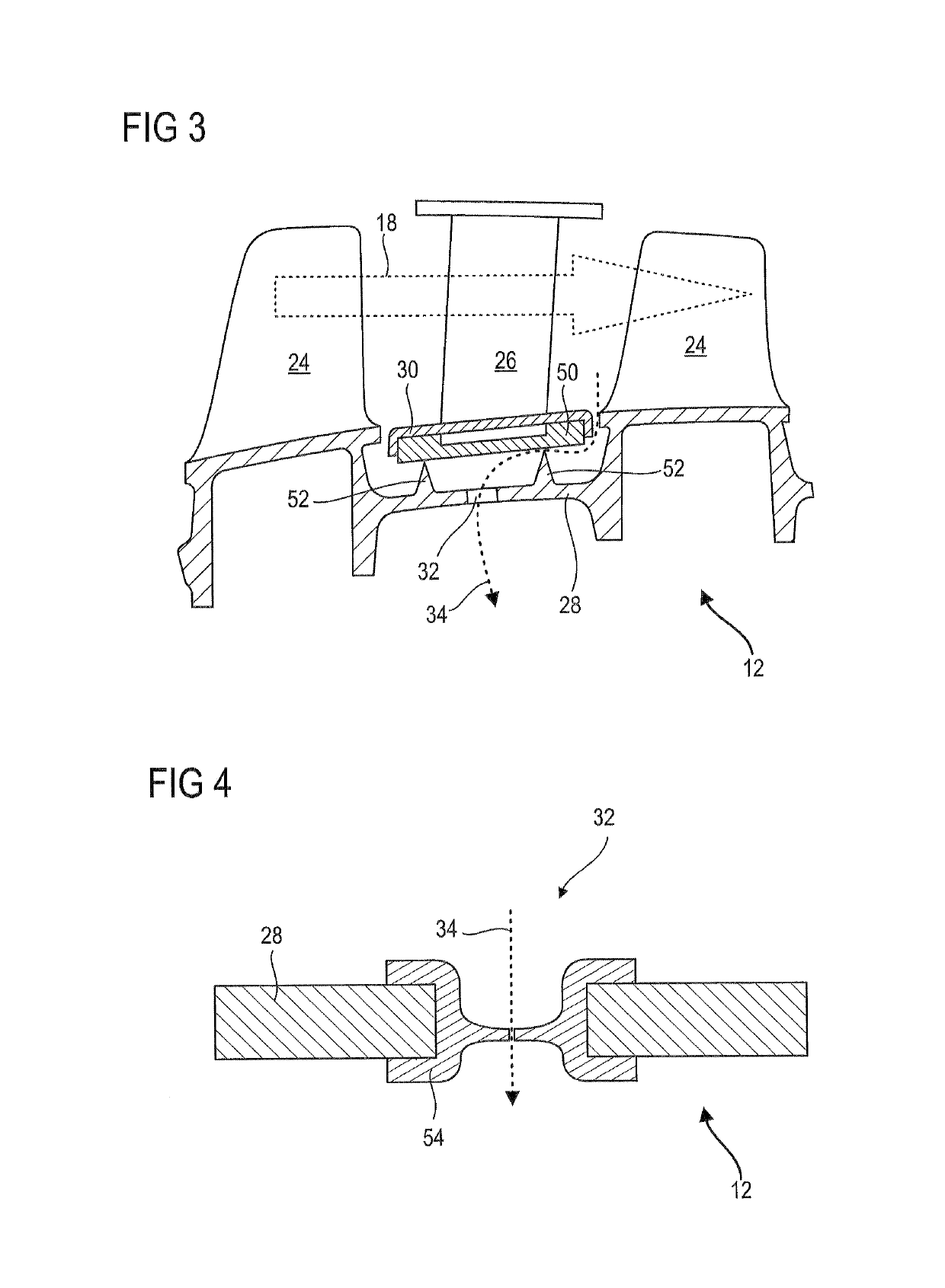
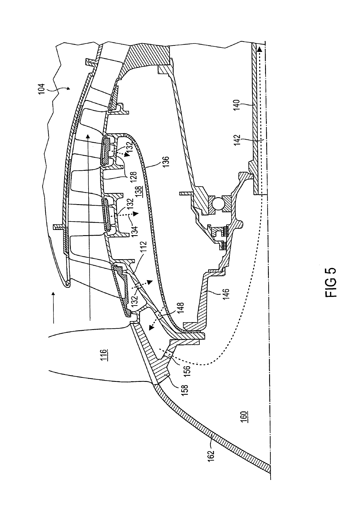
[0017]The object of the present application is a rotor of an axial turbine engine, in particular a drum of a compressor of an axial turbine engine, the rotor comprising: an annular outer wall delimiting a primary annular flow of the turbine engine, a sealing device formed on the wall, distinguished in that the annular wall comprises at least one intake orifice for leakages arranged at the axial level of the sealing device to divert the leakages therefrom so as to evacuate them axially beyond the rotor.

[0018]According to an advantageous embodiment of the present application, the wall surrounds a cylindrical or annular space which communicates with the intake o...


PUM


Abstract

A rotor, in particular a drum of a low-pressure compressor of a turbojet aero engine, is disclosed. The rotor includes an outer annular wall delimiting a primary annular flow of the turbine engine, sealing devices with two rubbing strips or annular ribs formed on the wall. The rubbing strips cooperate by abrasion with inner shrouds. In addition, the annular wall includes rows of intake orifices for leakages which are arranged between each pair of rubbing strips in order to aspirate the recirculation leakages there. A plenum for leakages is formed inside the rotor by means of a composite partitioning, then evacuates the parasitic flow downstream of the turbine engine via the central shaft.

Description

[0001]This application claims priority under 35 U.S.C. § 119 to Belgium Patent Application No. 2015 / 5416, filed 1 Jul. 2015, titled “Perforated Drum of a Compressor of an Axial Turbine Engine,” which is incorporated herein by reference for all purposes.BACKGROUND[0002]1. Field of the Application[0003]The present application relates to recirculation leakages at a bladed rotor of an axial turbine engine. The present application also concerns a compressor of an axial turbine engine. The present application also proposes an axial turbine engine such as a turbojet aero engine.[0004]2. Description of Related Art[0005]A compressor, like a turbine of a turbojet aero engine, has a series of rows of vanes. Some of these rows are linked to the stator and others linked to the rotor. The definition of the profile of the vanes allows the processing of annular flows, by causing them to be compressed or expanded to recover energy. The efficiency of these mechanical actions on the flow depends on ma...

Claims


Application Information

Patent Timeline
Patent Type & Authority Patents(United States)
IPC IPC(8): F01D11/00F04D29/52F04D29/32F04D29/16F04D29/08F04D27/00F01D11/04F02C6/08F04D29/54F04D29/68F01D5/06
CPCF04D29/682F01D5/06F01D11/001F01D11/04F02C6/08F04D27/009F04D29/164F04D29/321F04D29/522F04D29/542F04D29/083Y02T50/672F05D2260/6022F04D29/324F04D29/662Y02T50/60
Inventor HIERNAUX, STEPHANE
Owner TECHSPACE AERO
Why Eureka
Try Eureka