Softening strip for controlling stress in joints at very low temperatures

a softening strip and low temperature technology, applied in the field of composite tanks, can solve the problem that the softening strip cannot be re-machined to achieve the desired fit-up precision, and achieve the effect of reducing the amount of adhesive required to bond the softening strip to the structure, precise joint fit and thin bond lines

Active Publication Date: 2019-05-07
THE BOEING CO
View PDF5 Cites 0 Cited by
  • Summary
  • Abstract
  • Description
  • Claims
  • Application Information

AI Technical Summary

Benefits of technology

[0008]One of the advantages of the embodiments is that relatively thin bond lines of consistent thickness may be achieved between the softening strip and a structure to which it is bonded. Further, the amount of adhesive required to bond the softening strip to the structure is reduced.
[0009]Another advantage is that the OML surface of the softening strip can be modified after being bonded to the structure in order to account for installation tolerances and achieve a more precise fit in the joint. As a result, a substantially consistent, uniform softening strip OML is achieved facilitating installation.
[0010]A further advantage of the embodiments is that the thickness of a tip of the softening strip can be increased by bonding layers of rigid material opposite sides of the softening strip. Also, the layers of rigid material protect the softening strip against tearing during final machining on the softening strip after it is bonded to the structure.
[0011]A still further damage of the embodiments is that a softening strip is produced having tighter tolerances which improve the ability to locate and reference the softening strip to a structure during assembly.

Problems solved by technology

Precise fit-up and dimensional control of the softening strip is challenging for a number of reasons, including tolerance buildups during layup and machining of the softening strip, variability of adhesive bond line thicknesses, and the need to etch the softening strip prior to being bonded onto the tank, to name only a few.
Once bonded to the tank, the softening strip cannot be re-machined to achieve the desired fit-up precision.
A still further damage of the embodiments is that a softening strip is produced having tighter tolerances which improve the ability to locate and reference the softening strip to a structure during assembly.

Method used


Image

  • Softening strip for controlling stress in joints at very low temperatures
  • Softening strip for controlling stress in joints at very low temperatures
  • Softening strip for controlling stress in joints at very low temperatures

Examples


Embodiment Construction

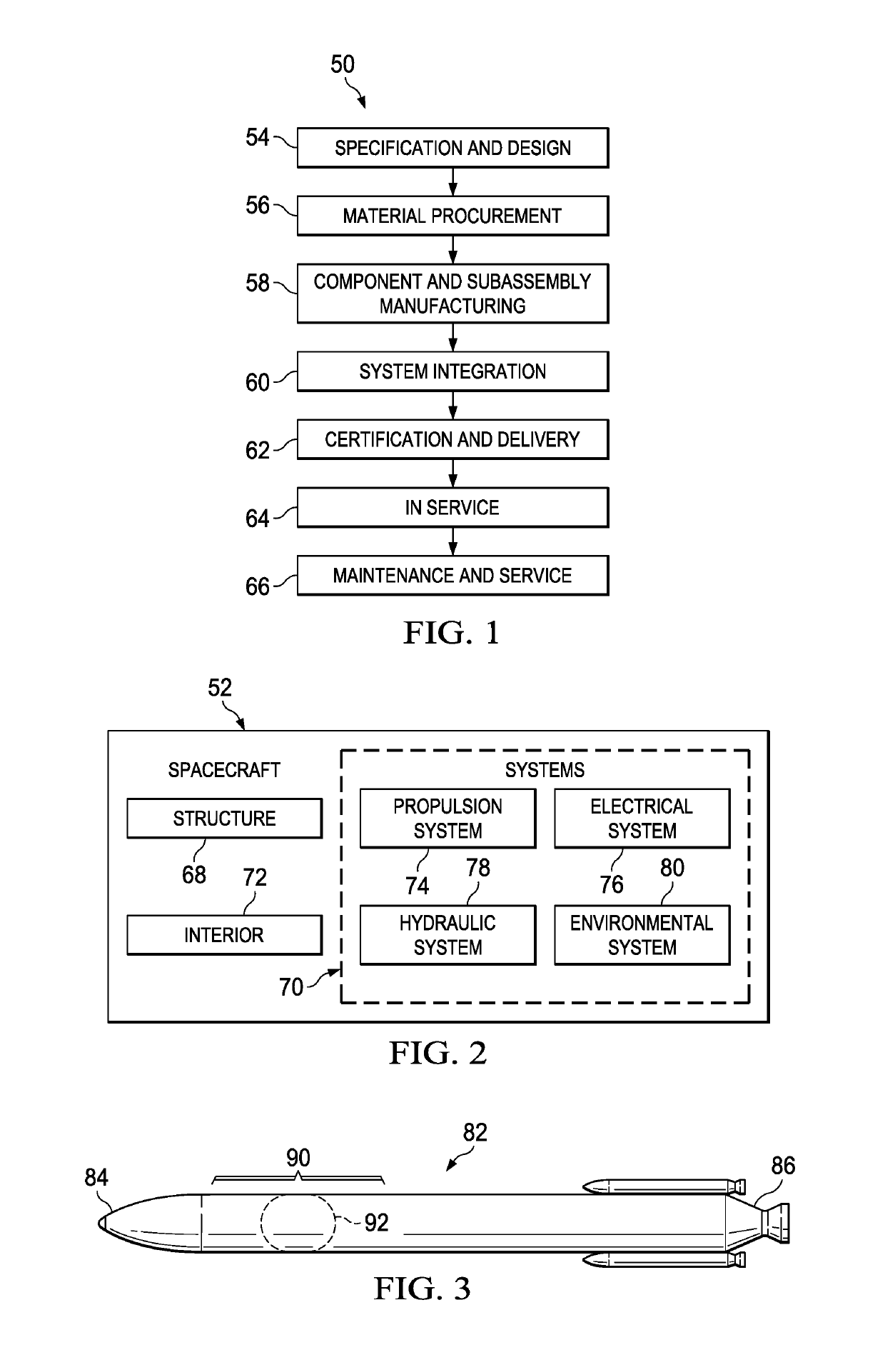
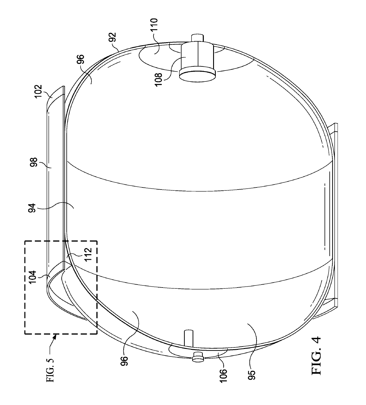
[0045]Referring to the drawings, embodiments of the disclosure may be described in the context of a spacecraft manufacturing and service method 50 shown in FIG. 1, and a spacecraft 52 shown in FIG. 2. During pre-production, exemplary spacecraft manufacturing and service method 50 may include specification and design 54 of the spacecraft 52 and material procurement 56. During production, component and subassembly manufacturing 58 and system integration 60 of spacecraft 52 in FIG. 2 takes place. Thereafter, the spacecraft 52 may go through certification and delivery 62 in order to be placed in service 64. While in service by a customer, spacecraft 52 scheduled for routine maintenance and service 66, which may include modification, reconfiguration, refurbishment, and other maintenance or service.

[0046]Each of the processes of spacecraft manufacturing and service method 50 may be performed or carried out by a system integrator, a third party, and / or an operator. In these examples, the o...


PUM

PropertyMeasurementUnit
temperaturesaaaaaaaaaa
cryogenic temperaturesaaaaaaaaaa
temperaturesaaaaaaaaaa

Abstract

A hybrid softening strip for controlling stresses in a joint at low temperatures includes a layer of sacrificial material that can be tailored to fit the softening strip in the joint after the softening strip has been bonded to a structure.

Description

BACKGROUND INFORMATION1. Field[0001]The present disclosure generally relates to composite structures that are subjected to very low temperatures, and deals more particularly with joints in composite tanks used in space exploration and launch vehicles to contain liquids such as propellants at cryogenic temperatures.2. Background[0002]Certain composite structures are specifically designed for use in very low temperature environments. For example, spacecraft and launch vehicles often use tanks to store solid propellants or liquid fuels at cryogenic temperatures. In one design, a composite tank includes a cylindrical outer wall provided with a cylindrical skirt that is joined to dome-shaped ends by a bonded lap joint that is Y-shaped in cross-section. In order to control peak shear stresses in the joint caused by high line loads, a wedge shaped softening strip is placed in a gap between the cylindrical skirt and the dome shaped ends. The softening strip is formed of composite materials ...

Claims


Application Information

Patent Timeline
Patent Type & Authority Patents(United States)
IPC IPC(8): B64G1/00B32B37/12B32B38/00B32B5/02B64G1/40
CPCB32B37/12B32B5/024B32B38/0012B32B2037/1253B32B2305/076B32B2313/04F17C2270/0197B32B2439/00B32B2605/18B64G1/002B64G1/402F17C2270/0194B32B2363/00
Inventor GUZMAN, JUAN CARLOSMCCARVILLE, DOUGLAS A.HAND, MICHAEL LESLIEROBINSON, MICHAEL JAMES
Owner THE BOEING CO
Why Eureka
Try Eureka