Spray coatable adhesive for bonding silicon dies to rigid substrates

a technology of rigid substrates and adhesives, applied in the direction of adhesive types, photomechanical devices, instruments, etc., can solve the problems of difficult dispense of such adhesives onto a dense surface, and achieve the effects of narrow width, low viscosity, and robust seal

Active Publication Date: 2011-12-29
FUNAI ELECTRIC CO LTD
View PDF8 Cites 2 Cited by
  • Summary
  • Abstract
  • Description
  • Claims
  • Application Information

AI Technical Summary

Benefits of technology

[0007]The present disclosure provides an adhesive composition having low viscosity and is spray coatable. This ease of application allows the adhesive composition of the present invention to be uniformly applied on a substrate having through holes and channels and form a robust seal with narrow widths. The adhesive composition of the present invention provides particularly good adhesion between a silicon die and a silicon substrate. This adhesive composition includes an epoxy based resin, a thermal acid generator, a photoacid generator and a solvent. The adhesive composition is spray coatable and can be cured upon exposure to radiation and heat, thus allowing chips to be bonded on a wafer level with precise placement. Further, the adhesive composition provides a robust seal at very narrow seal width of less than 400 μm and a thin bond line of less than 20 μm, thus maintaining good adhesion between a rigid silicon die and a silicon substrate in an ink jet printer environment.

Problems solved by technology

This miniaturization of ejection chips then leads to challenges relating to techniques and adhesive used for bonding the chips on the support substrate.
It becomes difficult to dispense such adhesives onto a densely patterned substrate allowing a bond line and sealing width much smaller than the adhesive dispensing width.

Method used

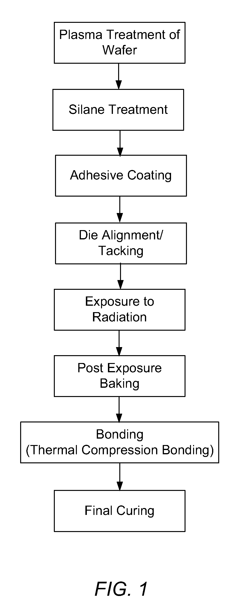
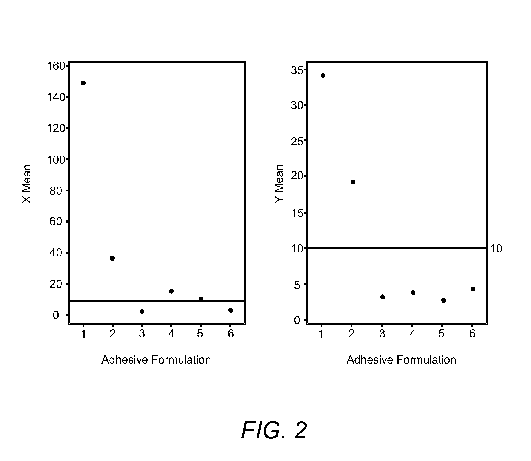
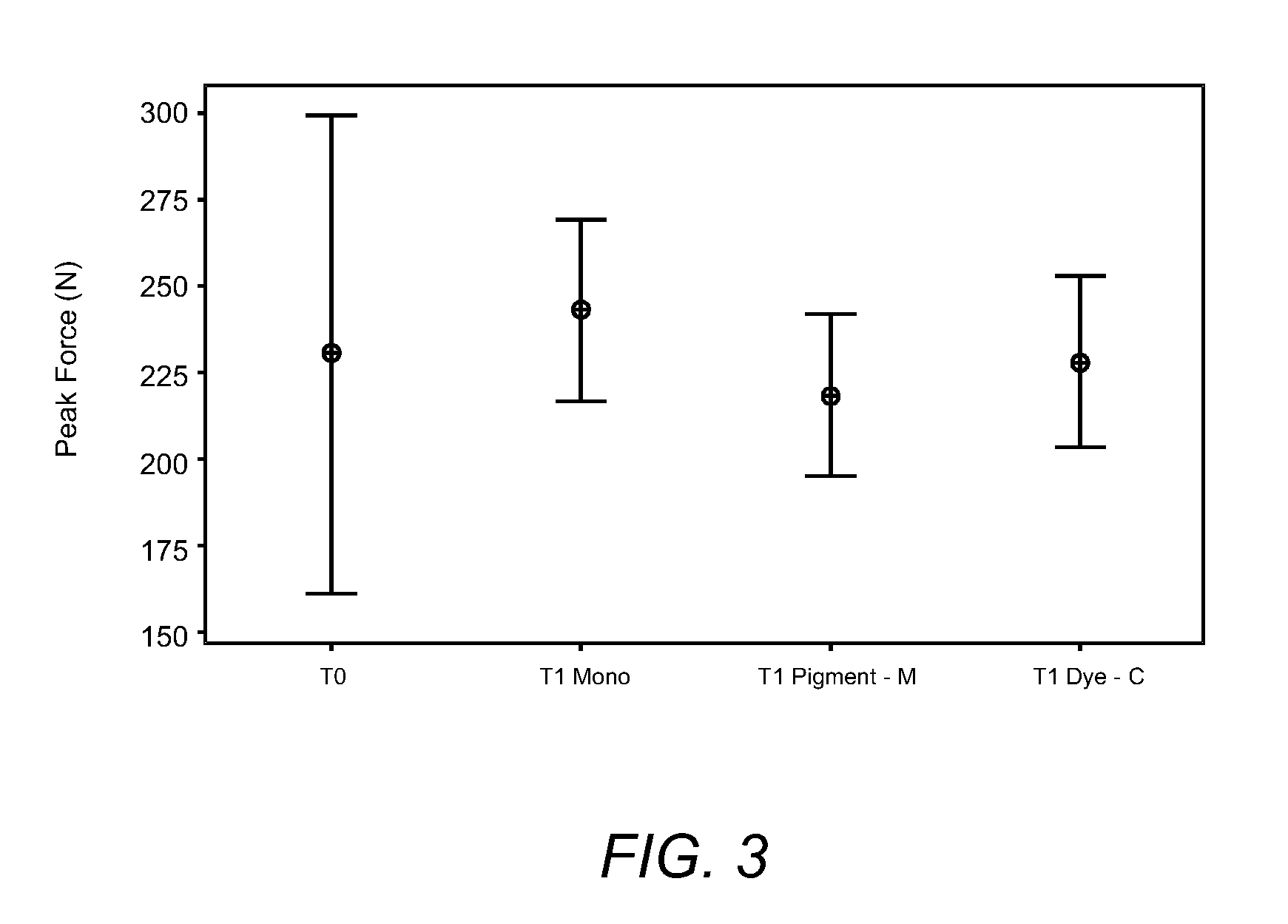

Image

  • Spray coatable adhesive for bonding silicon dies to rigid substrates
  • Spray coatable adhesive for bonding silicon dies to rigid substrates
  • Spray coatable adhesive for bonding silicon dies to rigid substrates

Examples


Embodiment Construction

[0012]It is to be understood that various omissions and substitutions of equivalents are contemplated as circumstances may suggest or render expedient, but these are intended to cover the application or implementation without departing from the spirit or scope of the claims of the present disclosure. It is to be understood that the present disclosure is not limited in its application to the heater chip of an ink jet printhead set forth in the following description. The present disclosure is capable of other embodiments and of being used in various applications. Also, it is to be understood that the phraseology and terminology used herein is for the purpose of description and should not be regarded as limiting. The use of “including,”“comprising,” or “having” and variations thereof herein is meant to encompass the items listed thereafter and equivalents thereof as well as additional items. Further, the terms “a” and “an” herein do not denote a limitation of quantity, but rather denot...


PUM

PropertyMeasurementUnit
widthaaaaaaaaaa
widthaaaaaaaaaa
glass transition temperatureaaaaaaaaaa

Abstract

A spray coatable adhesive composition used for bonding silicon dies to a rigid substrate, preferable a silicon substrate is disclosed. The adhesive composition includes an epoxy based resin, a thermal acid generator, a photoacid generator and a solvent. The epoxy based resin includes a mixture of a solid bisphenol A epoxy resin and a liquid or semi-liquid hydrogenated bisphenol A epoxy resin at a weight ratio ranging from about 80:20 to about 65:35. The adhesive composition has a low viscosity which allows it to be spray coated on a rigid substrate and form thin film adhesive which allows silicon dies to be bonded with precise placement on the silicon substrate.

Description

CROSS REFERENCES TO RELATED APPLICATIONS[0001]This patent application is related to and claims the priority to U.S. Provisional Patent Application Ser. No. 61 / 358,179, filed Jun. 24, 2010, entitled “Formula and Process for Ejection Chips in Micro-fluid Applications” and assigned to the assignee of the present application.STATEMENT REGARDING FEDERALLY SPONSORED RESEARCH OR DEVELOPMENT[0002]None.REFERENCE TO SEQUENTIAL LISTING, ETC.[0003]None.BACKGROUND1. Field of the Invention[0004]The present disclosure generally relates to micro-fluid ejection devices, such as inkjet printers. More particularly, although not exclusively, it relates to spray coatable adhesive used for bonding silicon chips of ejection heads to rigid substrates.2. Description of the Related Art[0005]In the field of micro-fluid ejection devices, ink jet printers are an example application where miniaturization continues to be pursued. This includes miniaturization of ejection chips or dies to reduce material cost of e...

Claims


Application Information

Patent Timeline
Patent Type & Authority Applications(United States)
IPC IPC(8): C09J163/00
CPCB41J2/1601B41J2/1645B41J2/1628B41J2/1623
Inventor WU, XIAOMINGDRYER, PAULRHINE, DAVIDPEARSON, ANNASINGH, JEANNE MARIE SALDANHAWELLS, RICHARDPROVENCE, JOEL
Owner FUNAI ELECTRIC CO LTD
Why Eureka
Try Eureka