System and method for vacuum bag fabrication

a vacuum bag and vacuum bag technology, applied in the field of adhesive bonding and laminating, can solve the problems of low void content, air trapped in the bond line, etc., and achieve the effect of reducing the amount of trapped air

Inactive Publication Date: 2005-08-11
RAYTHEON CO
View PDF3 Cites 6 Cited by
  • Summary
  • Abstract
  • Description
  • Claims
  • Application Information

AI Technical Summary

Benefits of technology

[0017] The present invention is a system and method for vacuum bag assembly fabrication via the vacuum bag method which reduces the amount of trapped air. The inventive system includes a chamber adapted to contain a vacuum bag and first and second evacuating mechanisms. The first evacuating mechanism serves to evacuate the bag and vent to atmosphere. The second evacuating mechanism serves to evacuate and vent the chamber to atmosphere.
[0030] Curing may be accomplished by subjecting the curable composition to sufficient heat for a sufficient time to effect a complete cure with optimum interlaminar bond strength. This is the standard method. Adhesive and resin manufacturers always provide the optimum cure schedules for the materials they provide. However, in an improvement on the standard method, which provides for easy reworking of the assembly via producing less than optimum interlaminar bond strength, especially an assembly of bonded components, the temperature is increased at a fast rate to specification cure temperature. The preferred rate is about 8-12° C. per minute. The double vacuum bonding method disclosed herein results in nearly void free bond lines. This enables utilization of adhesive joints with lesser strength adhesives or with thinner bond lines.

Problems solved by technology

The vacuum draws out some volatiles and trapped air, resulting in a low void content.
If the bag wrinkles against the hard assembly, it will trap air.
While vacuum bagging is a good and inexpensive method of fabricating adhesively bonded assemblies, because of the relatively low pressures employed, a fairly thick bond line results and air can still be trapped in the bond line.
However, good adhesion makes rework difficult.
If the adhesion is too good, it may not be possible to disassemble the parts even with heating of the adhesive.

Method used


Image

  • System and method for vacuum bag fabrication
  • System and method for vacuum bag fabrication
  • System and method for vacuum bag fabrication

Examples


Embodiment Construction

[0037] While the present invention is described herein with reference to illustrative embodiments for particular applications, it should be understood that the invention is not limited thereto. Those having ordinary skill in the art and access to the teachings provided herein will recognize additional modifications, applications, and embodiments within the scope thereof and additional fields in which the present invention would be of significant utility.

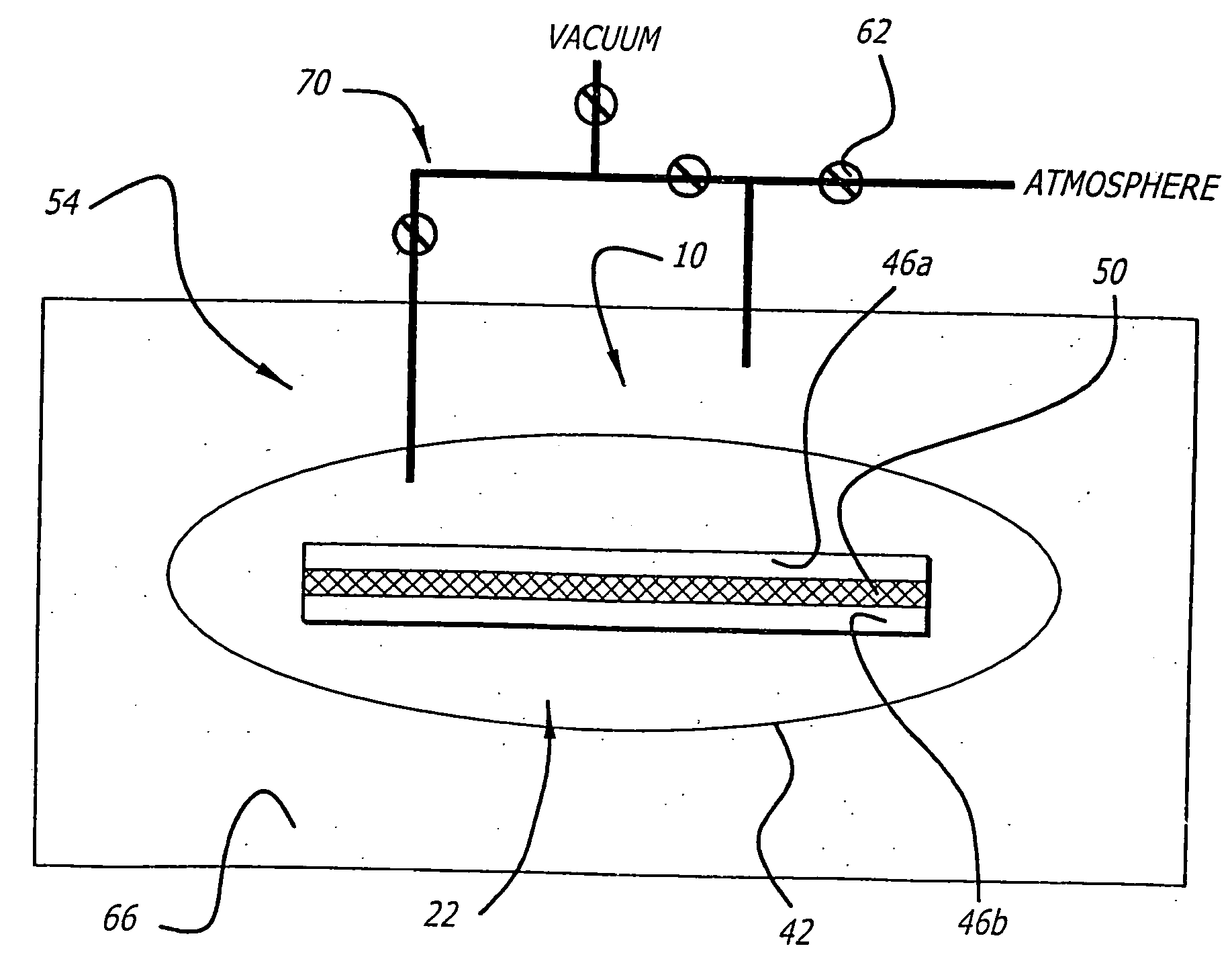
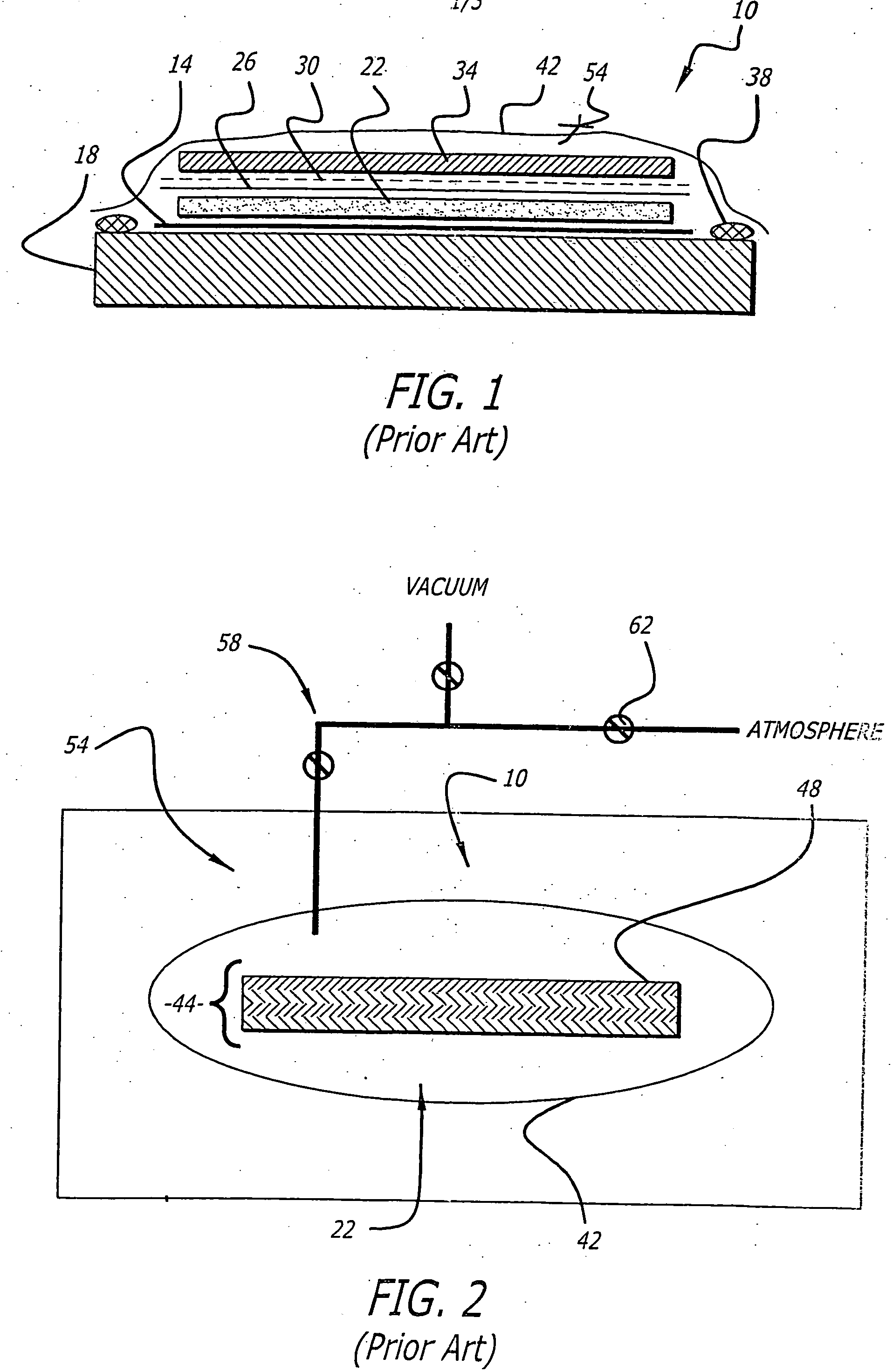
[0038]FIG. 1 illustrates construction of a typical vacuum bag lay up 10. A layer of release agent 14 is placed on the tool 18. The assembly 22 is placed on top of the release agent 14. On top of that is placed a tear ply 26 (if needed), a release film 30 and a bleeder 34. Sealant 38 is laid around the assembly 22 at the edge of the tool 18. The bag 42 is laid over the entire assembly and finally a vacuum fitting 54 is installed through the bag 42.

[0039] The lay up 10 just described is generic. It can be used for lamination of compo...


PUM

PropertyMeasurementUnit
atmospheric pressureaaaaaaaaaa
lap shear strengthaaaaaaaaaa
lap shear strengthsaaaaaaaaaa

Abstract

A system and method for vacuum bag assembly fabrication via the vacuum bag method which reduces the amount of trapped air. The inventive system includes a chamber adapted to contain a vacuum bag and first and second evacuating mechanisms. The first evacuating mechanism serves to evacuate the bag and vent to atmosphere. The second evacuating mechanism serves to evacuate and vent the chamber to atmosphere. Thus, generally, the inventive method includes the steps of placing a vacuum bag lay up in an air tight chamber; and evacuating the vacuum bag lay up and the air tight chamber at the same time. In practice, the assembly would consist of at least two components and a heat curable composition. The components can be parts to be bonded together or layers of cloth to be made into a laminate. In this case, the heat curable composition would be a catalyzed adhesive or resin.

Description

STATEMENT REGARDING FEDERALLY SPONSORED R&D [0001] This invention was made with Government support under Contract No. F33657-91-C-0006 awarded by the Department of the Air Force. The U.S. Government has certain rights in this invention.BACKGROUND OF THE INVENTION [0002] 1. Field of Invention [0003] This invention relates to the field of adhesive bonding and laminating. Specifically, the present invention relates to systems and methods for bonding and laminating using atmospheric pressure, commonly known as vacuum bagging. [0004] 2. Description of the Related Art [0005] Vacuum bagging is one of a variety of methods used for the bonding and laminating of manufactured parts. Generally speaking, the part being bonded or laminated is surrounded by an airtight membrane or diaphragm; a vacuum is pulled on that membrane; and the surrounding pressure forces the membrane tightly to the part. Once the part is vacuum bagged it is allowed to cure for a specific period of time depending on its co...

Claims


Application Information

Patent Timeline
Patent Type & Authority Applications(United States)
IPC IPC(8): B29C70/00
CPCB32B2309/68B32B37/1018
Inventor CIAMBRONE, DAVID F.JOHNSON, KIRK E.AHMAD, HOSSEIN
Owner RAYTHEON CO
Why Eureka
Try Eureka