
Process for selective ethylene oligomerization with antifouling components

a selective ethylene and oligomerization technology, applied in the direction of organic-compound/hydride/coordination complex catalyst, physical/chemical process catalyst, bulk chemical production, etc., can solve the problems of polyethylene-based residue formation, process undesirable, and increasing process shutdown

Active Publication Date: 2019-05-07
SAUDI ARABIAN OIL CO +1
View PDF34 Cites 25 Cited by
  • Summary
  • Abstract
  • Description
  • Claims
  • Application Information

AI Technical Summary

Benefits of technology

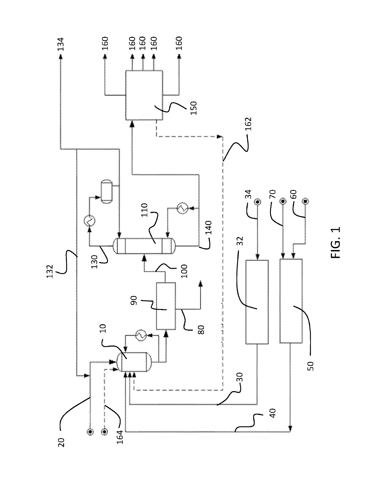
The patent aims to provide better reactor systems and methods to prevent polymeric fouling on reactor system walls and tubes while still achieving the desired oligomerization rate and selectivity to form desired reaction products.

Problems solved by technology

However, the process for isolating 1-butene from such an effluent requires several difficult process steps that may make the process undesirable.
There is a known problem with oligomerization systems: polymer formation.
Long residence times and poor heat removal from the highly exothermic reactions lead to the formation of polyethylene-based residues.
A side effect of chronic fouling is increasingly frequent process shutdowns and higher maintenance costs for removing adhered polymer residues.
Additionally, a polymer coating along the wall of a reactor may act as an insulator, which may negatively affect heat transfer to the reactor system.
Polymer deposits may also collect debris that can poison the reaction process.
An especially troublesome issue is the formation of “hot spots”.
A hot spot is an area where external cooling is ineffective and catalyst activity is high.
It represents a loss of process control.
If left unchecked, the hot spot can eventually lead to a process shutdown due to the loss of cooling capacity, a runaway polymerization reaction, or both.

Method used


Image

  • Process for selective ethylene oligomerization with antifouling components
  • Process for selective ethylene oligomerization with antifouling components
  • Process for selective ethylene oligomerization with antifouling components

Examples


examples

[0059]The various embodiments of antifouling catalyst systems and the performance of the antifouling compound injection system will be further clarified by the following examples. The examples are illustrative in nature, and should not be understood to limit the subject matter of the present disclosure.

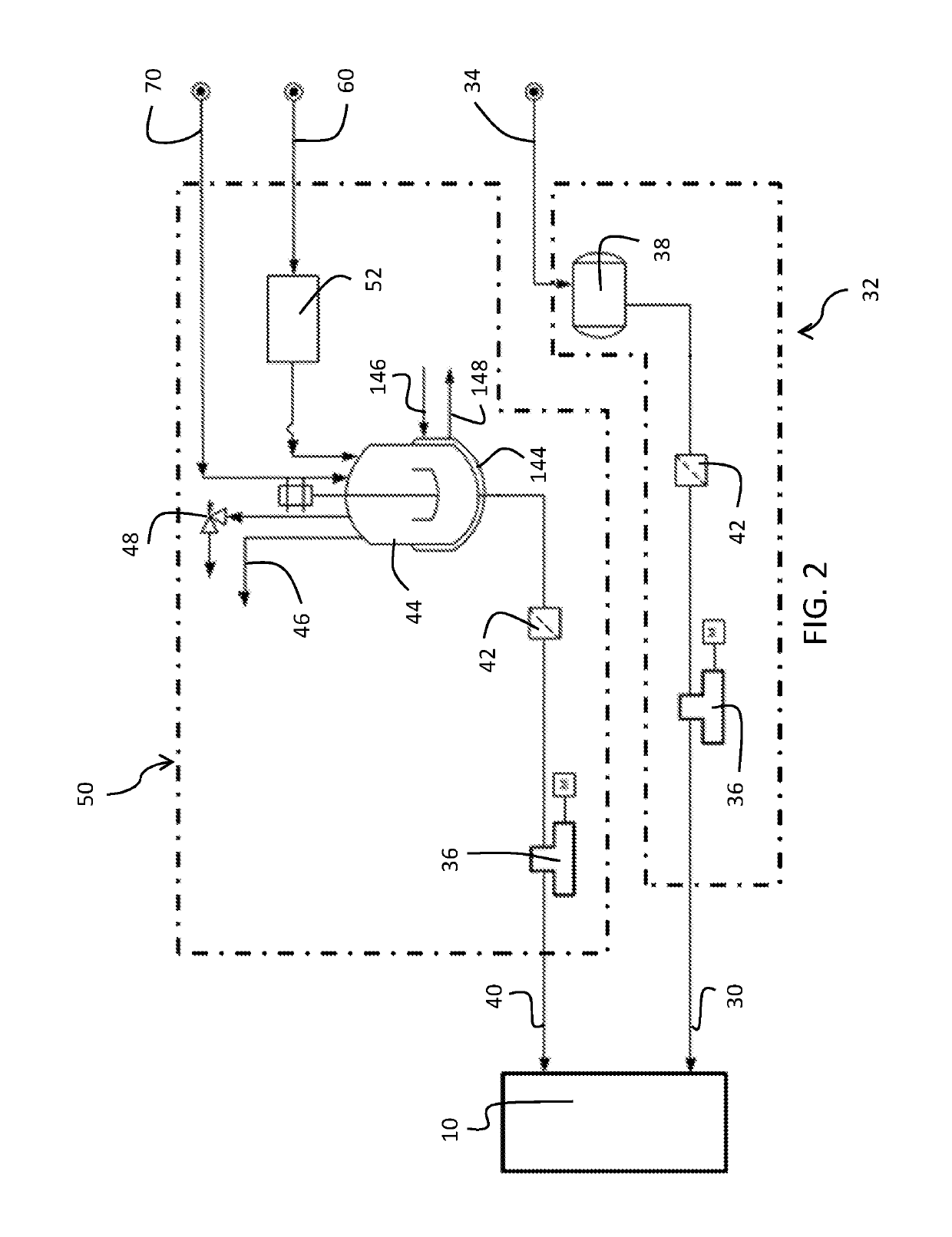
[0060]To evaluate the antifouling effects of the antifouling catalyst systems and processes described, ethylene dimerization reactions were carried out and evaluated. Multiple sample antifouling catalyst systems were formulated and tested in accordance with the processes of this disclosure. The process for selective ethylene dimerization with antifouling components and the associated antifouling compound injection system were compared to baseline comparative systems. Specifically, with the antifouling compound injection system, the co-catalyst and the antifouling agent were premixed in the antifouling compound mixing vessel before injection into the process reactor as a separate strea...


PUM

PropertyMeasurementUnit
temperatureaaaaaaaaaa
pressureaaaaaaaaaa
temperatureaaaaaaaaaa

Abstract

A process for selectively producing 1-butene comprises contacting at least one antifouling agent with at least one aluminum alkyl compound to form at least one antifouling compound in a first step. The antifouling compound may comprise a structure comprising a central aluminum molecule bound to an R1 group, bound to an R2 group, and bound to an R3 group. The process further comprises feeding the antifouling compound, an additional amount of the aluminum alkyl compound, at least one titanate compound, and ethylene into a reactor to dimerize ethylene in a second step. The titanate compound is fed as a stream separated from the streams of the antifouling compound and the additional amount of the aluminum alkyl compound. The molar ratio of the sum of the aluminum alkyl compound to the titanate compound is equal to or higher than 1.5 and equal to or lower than 3.0.

Description

CROSS-REFERENCE TO RELATED APPLICATIONS[0001]This application claims the benefit of U.S. Provisional Application Ser. No. 62 / 431,049 filed Dec. 7, 2016, incorporated herein by reference.BACKGROUNDField[0002]Embodiments of the present disclosure generally relate to processes and catalyst systems used in ethylene oligomerization and, more specifically, relate to processes and antifouling catalyst systems used in ethylene oligomerization which reduce undesired polymerization.Technical Background[0003]1-Butene and 1-hexene are important petrochemicals, especially for the productions of polyethylene. The reaction of ethylene and other alpha-olefins, especially 1-butene and 1-hexene, forms various grades of linear low density polyethylene (LLDPE), a useful commercial polymer. A source of 1-butene is the butene fraction from the effluent of a hydrocarbon cracker, such as a steam cracker or fluidized catalytic cracker. However, the process for isolating 1-butene from such an effluent requir...

Claims


Application Information

Patent Timeline
Patent Type & Authority Patents(United States)
IPC IPC(8): C07C2/30C07C2/32C07C11/08
CPCC07C2/30C07C2/32C07C11/08C07C2531/14C07C2531/22Y02P20/52B01J31/22B01J31/143B01J2531/46
Inventor SOGO, KENJISHAIKH, SOHEL K.ZHANG, ZHONGLINXU, WEIKASHIWAME, YOHEI
Owner SAUDI ARABIAN OIL CO
Learn More