
Hybrid metal-composite drive shaft unit and method of manufacturing same

a metal-composite drive shaft and hybrid technology, applied in the direction of mechanical equipment, transportation and packaging, other domestic objects, etc., can solve the problems of high cost of hybrid metal-composite drive shaft manufacturing, laborious and time-consuming manufacturing of this hybrid metal-composite drive shaft unit, etc., to reduce manufacturing steps, short cycle time, and easy and quick manufacturing

Active Publication Date: 2019-05-07
AIRBUS HELICOPTERS DEUT GMBH +1
View PDF37 Cites 2 Cited by
  • Summary
  • Abstract
  • Description
  • Claims
  • Application Information

AI Technical Summary

Benefits of technology

The present invention provides a new hybrid metal-composite drive shaft unit that is easy and quick to manufacture, with reduced manufacturing steps and short cycle times. The unit provides high operation stability and robustness. This solution solves the manufacturing problem of traditional drive shaft units, which are difficult to manufacture and have low stability and durability.

Problems solved by technology

However, manufacturing of this hybrid metal-composite drive shaft unit is laborious, complex and time-consuming, as multiple process steps including attachment of the inner tube to the metal drive shaft connectors using the pins, wounding the fibers around the tube and the pins to defines zones of reinforcement, introducing the complete assembly into a molding machine and forming a plastic matrix around the fibers and the inner tube, are required.
Furthermore, due to the high number of required components, material and process steps, manufacturing of this hybrid metal-composite drive shaft unit and, thus, the hybrid metal-composite drive shaft as such are comparatively expensive.
However, manufacturing of this hybrid metal-composite drive shaft unit requires a final curing step, which is comparatively time-consuming and involves comparatively long cycle times. Therefore, manufacturing of this hybrid metal-composite drive shaft unit and, thus, the hybrid metal-composite drive shaft as such are complex and comparatively expensive.
However, manufacturing of this hybrid metal-composite drive shaft unit requires suitable evacuation and curing steps, and is, therefore, comparatively time-consuming and involves comparatively long cycle times. Accordingly, manufacturing of this hybrid metal-composite drive shaft unit and, thus, the hybrid metal-composite drive shaft as such are laborious and comparatively expensive.
However, all of these hybrid metal-composite drive shaft units are comparatively difficult and complex to manufacture and underlying manufacturing methods are comparatively laborious, time-consuming and frequently based on manual lay-up processes, so that the resulting hybrid metal-composite drive shaft units are usually relatively expensive.

Method used


Image

  • Hybrid metal-composite drive shaft unit and method of manufacturing same
  • Hybrid metal-composite drive shaft unit and method of manufacturing same
  • Hybrid metal-composite drive shaft unit and method of manufacturing same

Examples


Embodiment Construction

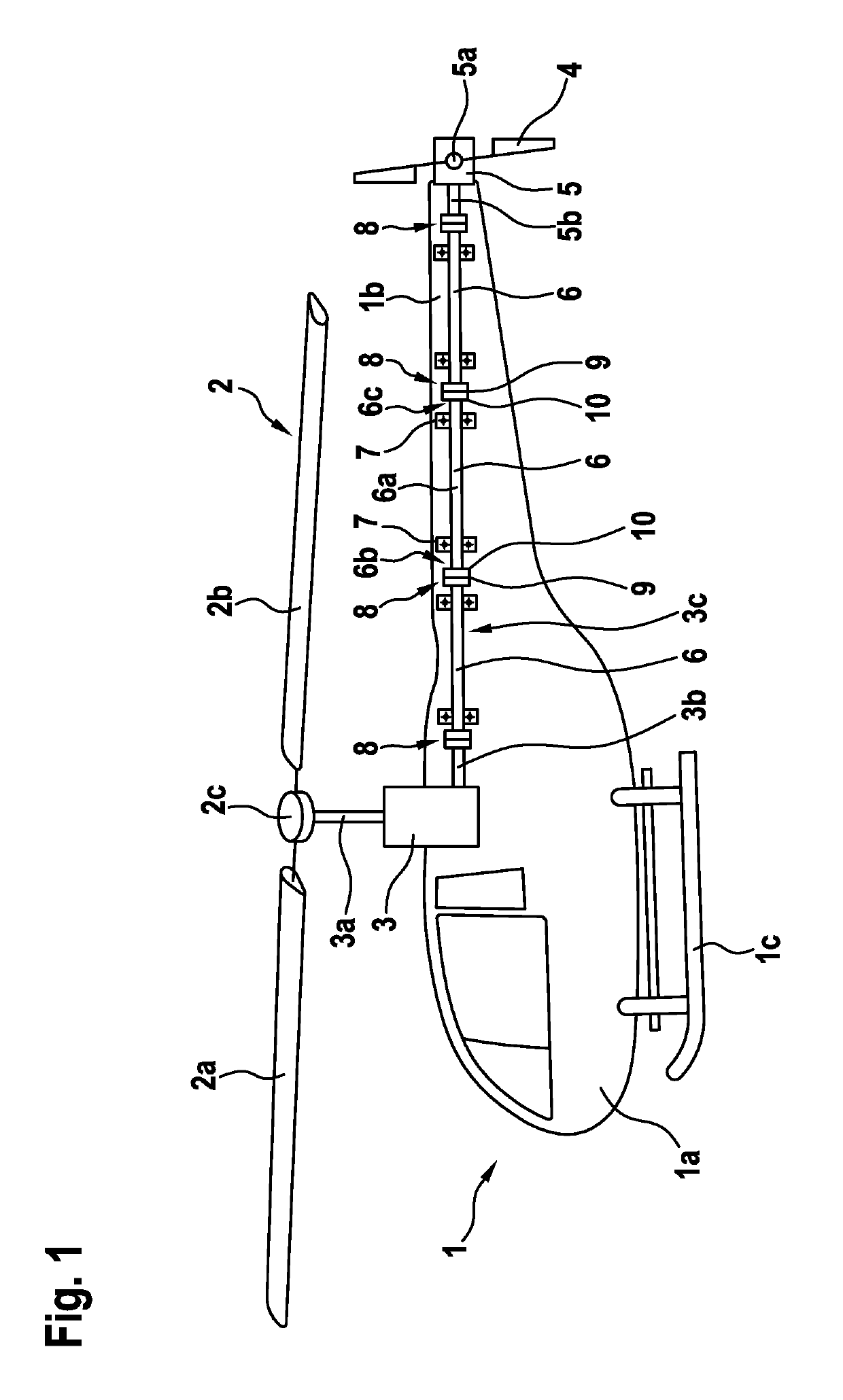
[0081]FIG. 1 shows a rotary-wing aircraft 1 according to the present invention. This rotary-wing aircraft 1 preferably comprises at least one main rotor 2, which is driven by a main gearbox 3 and illustratively embodied as a multi-blade rotor having at least two rotor blades 2a, 2b that are connected to a rotor head 2c. The rotary-wing aircraft 1 preferably further comprises at least one anti-torque rotor 4, which is driven by a tail gearbox 5 and illustratively embodied as a tail rotor.

[0082]According to one aspect, the main gearbox 3 is provided with at least one first and one second output shaft 3a, 3b. The first output shaft 3a couples the main gearbox 3 to the main rotor 2 for power transmission to the latter. The second output shaft 3b couples the main gearbox 3 via a power transmission line 3c to an input shaft 5b of the tail gearbox 5. The latter is illustratively provided with at least one output shaft 5a and adapted to transmit power received via the input shaft 5b by mean...


PUM

PropertyMeasurementUnit
winding anglesaaaaaaaaaa
angleaaaaaaaaaa
anglesaaaaaaaaaa

Abstract

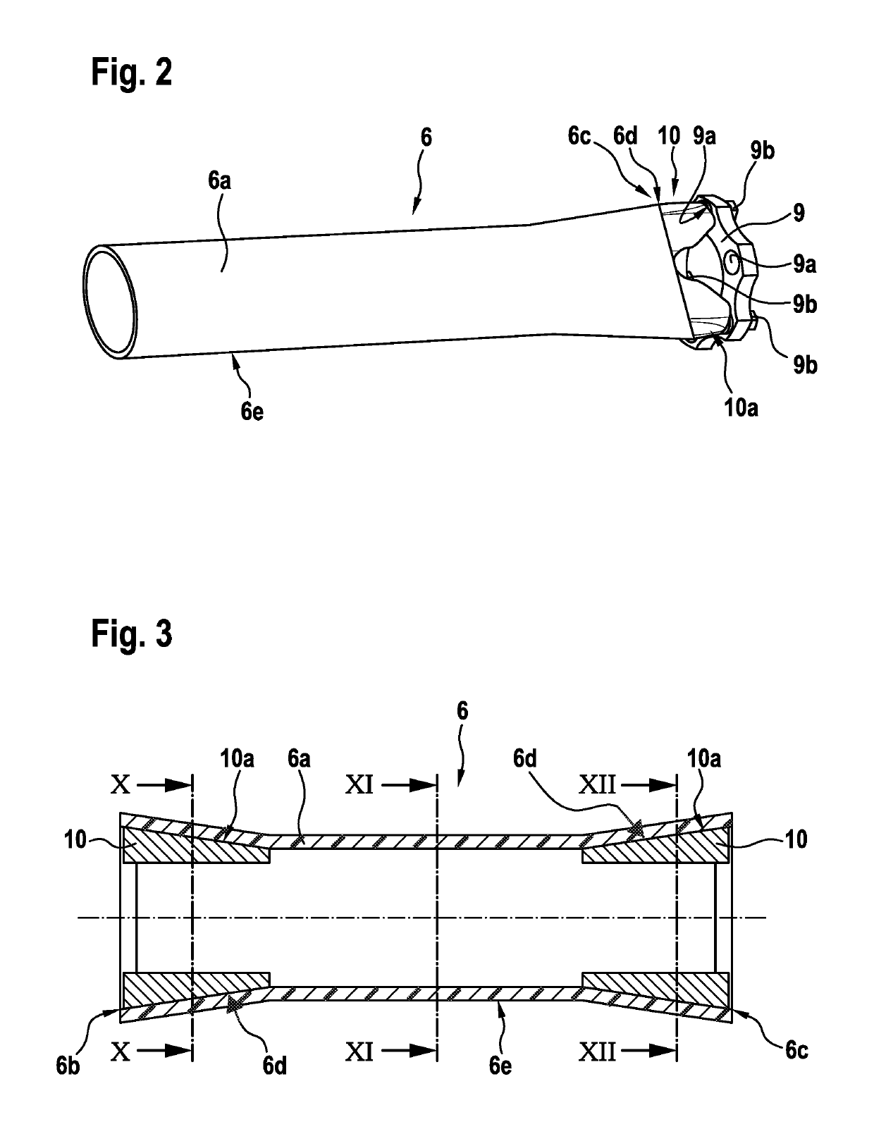
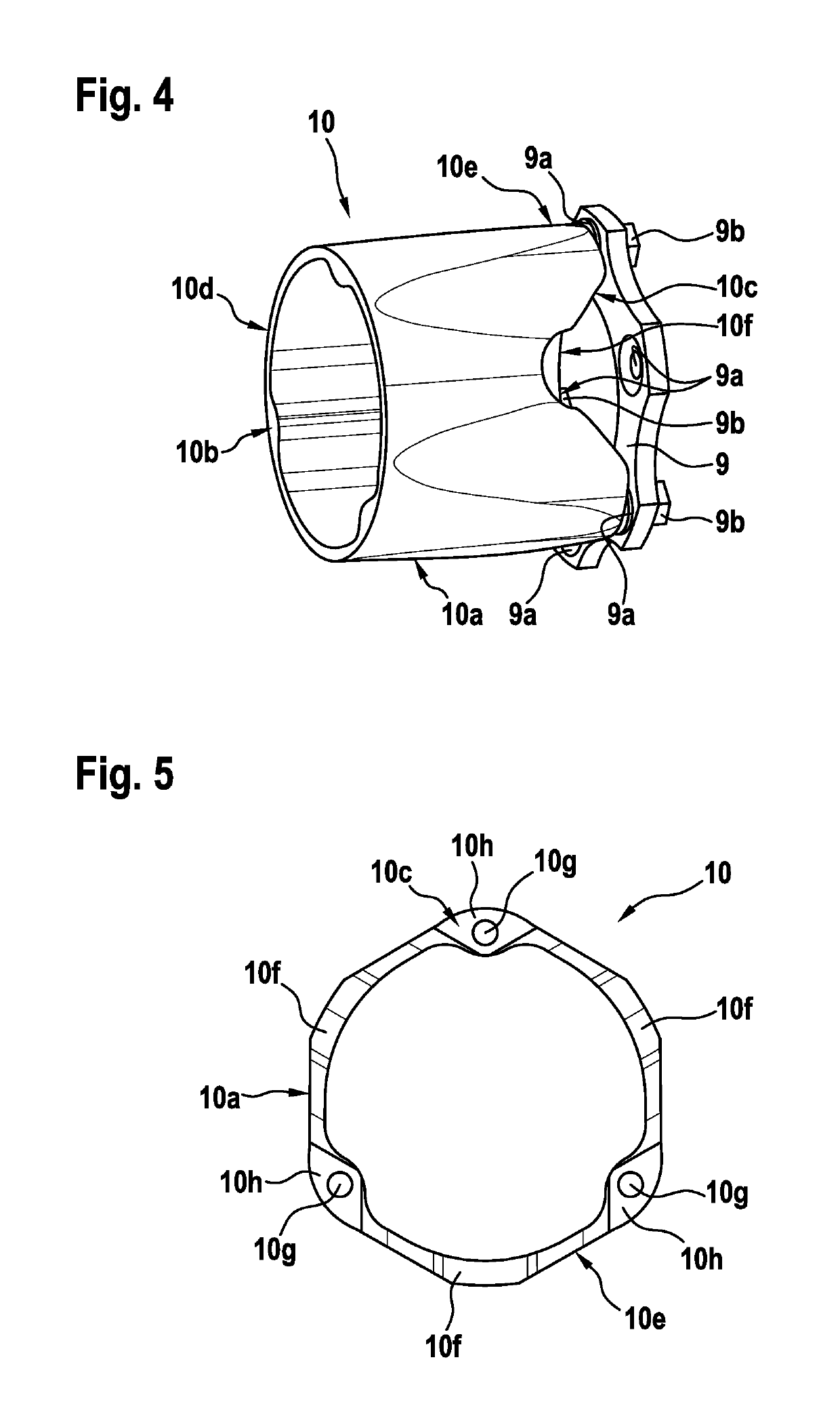
A hybrid metal-composite drive shaft unit, which comprises at least one metal drive shaft connector that is at least partly embedded into a composite drive shaft, the composite drive shaft comprising a thermoplastic polymer and being connected to the at least one metal drive shaft connector by means of a welded connection that defines a first load path for transmission of loads between the at least one metal drive shaft connector and the composite drive shaft, the at least one metal drive shaft connector and the composite drive shaft comprising, in the region of the welded connection, at least partly a polygonal cross-sectional shape for forming a form-fit connection that defines a second load path for transmission of loads between the composite drive shaft and the at least one metal drive shaft connector.

Description

CROSS REFERENCE TO RELATED APPLICATION[0001]This application claims priority to European patent application No. EP 15400017.8 filed on Apr. 16, 2015, the disclosure of which is incorporated in its entirety by reference herein.BACKGROUND OF THE INVENTION(1) Field of the Invention[0002]The invention is related to a hybrid metal-composite drive shaft unit for power transmission in a rotary-wing aircraft, said hybrid metal-composite drive shaft unit comprising the features of claim 1. The invention is further related to a coupling adapter for coupling such a hybrid metal-composite drive shaft unit to another drive shaft unit, and to a rotary-wing aircraft that is provided with such a hybrid metal-composite drive shaft unit. The invention is moreover related to a method of manufacturing such a hybrid metal-composite drive shaft unit.(2) Description of Related Art[0003]In a rotary-wing aircraft, such as a helicopter, a main gearbox that is adapted for driving a main rotor is usually conne...

Claims


Application Information

Patent Timeline
Patent Type & Authority Patents(United States)
IPC IPC(8): F16C3/02B29C65/02B64C27/14B29L31/30
CPCF16C3/023B29C65/02B64C27/14F16C3/026Y10T403/7098B29L2031/3076Y10T403/472Y02T50/40
Inventor REMER, NIKLASBORTOLOTTO, LAURENTJUERGENS, MICHAELEHARD, STEFAN
Owner AIRBUS HELICOPTERS DEUT GMBH
Learn More