
Converter, illuminator, and light sheet fluorescence microscope

a fluorescence microscope and light sheet technology, applied in the field of can solve the problems of insufficient image of fluorescence emitted from outside the dof, insufficient wide field of view (fov) and high z-direction resolution of typical light sheet fluorescence microscopes, etc., to achieve the effect of improving image quality and fast image acquisition

Active Publication Date: 2019-06-04
DAINIPPON SCREEN MTG CO LTD +1
View PDF6 Cites 3 Cited by
  • Summary
  • Abstract
  • Description
  • Claims
  • Application Information

AI Technical Summary

Benefits of technology

This patent is about a device that combines a converter, an illuminator, and a light sheet fluorescence microscope. The device allows for faster image acquisition and improved image quality using structured illumination or pivoting illumination. The control of the illumination profile is enabled by a high-speed spatial light modulator, which ensures precise and efficient lighting of the microscope. Overall, this invention allows for faster and higher-quality image acquisition using advanced illumination techniques.

Problems solved by technology

The first point that needs improvement is that the conventional technique fails to achieve both a wide field of view (FOV) and a high Z-direction resolution.
Thus, a typical light sheet fluorescence microscope sacrifices the Z-direction resolution.
Thus, the fluorescence emitted from outside the DOF is not imaged sufficiently and forms a blurred image that does not clearly indicate sample structure information.
This makes it difficult to achieve a high contrast image of a highly scattering sample.
Faster image acquisition is thus difficult in the light sheet fluorescence microscope.
For this reason, the limitation of the frequency of the structured illumination by the size of the focused beam waist tends to inhibit an improvement in sectioning capability.
Additionally, the system tends to be complicated because, for example, the DSLM-SI needs to bring the modulation by the AOM into synchronization with scanning by the galvanometer mirror.
The speed of switch of the propagation direction is thus limited by the scanning speed of the galvanometer mirror.
Faster image acquisition is difficult in pivoting illumination.
As described above, the conventional structured illumination and pivoting illumination have a problem of the difficulty in acquiring an image at higher speed.
Additionally, the conventional structured illumination has a problem of the difficulty in increasing the frequency of the structured illumination.

Method used


Image

  • Converter, illuminator, and light sheet fluorescence microscope
  • Converter, illuminator, and light sheet fluorescence microscope
  • Converter, illuminator, and light sheet fluorescence microscope

Examples


Embodiment Construction

[0045]1. Light Sheet Fluorescence Microscope

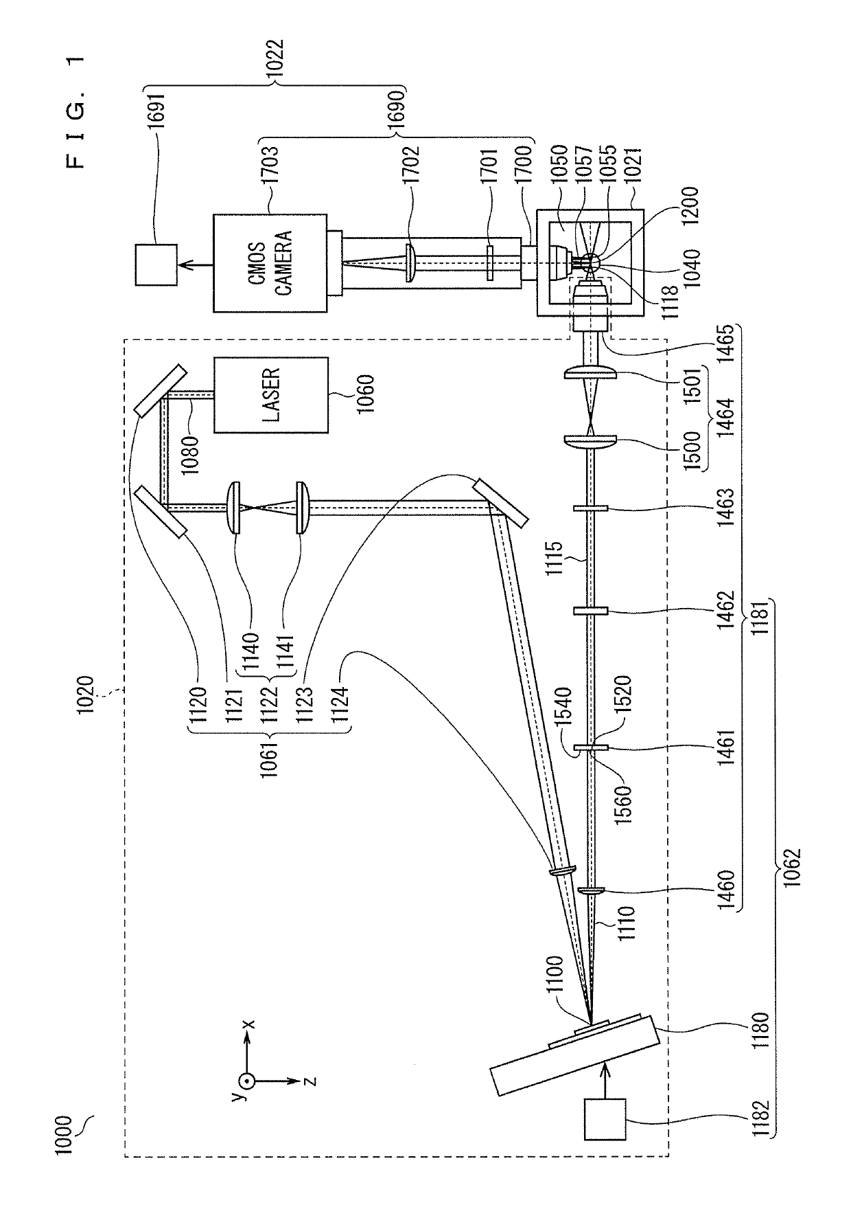
[0046]FIG. 1 is a schematic diagram illustrating a section of a light sheet fluorescence microscope of a first embodiment. FIG. 1 also illustrates coordinate axes indicating an xyz orthogonal coordinate system fixed in the light sheet fluorescence microscope of the first embodiment.

[0047]A light sheet fluorescence microscope 1000 illustrated in FIG. 1 includes an illuminator 1020, a sample chamber 1021, and an imaging device 1022. The light sheet fluorescence microscope 1000 may include components other than these components.

[0048]In the observation of a sample 1040 by the light sheet fluorescence microscope 1000, the sample 1040 is labeled by a fluorescent dye, and the labeled sample 1040 is housed in a space 1050 defined in the sample chamber 1021. The illuminator 1020 illuminates the housed sample 1040 from the x direction by a light sheet 1055 positioned parallel to the xy plane. The light sheet 1055 is a sheet-shaped illumination ligh...


PUM

PropertyMeasurementUnit
wavelengthaaaaaaaaaa
diameteraaaaaaaaaa
diameteraaaaaaaaaa

Abstract

Improved image quality by structured illumination or pivoting illumination and faster image acquisition are both achieved. A line light enters first to fifth virtual pixels of a grating light valve, and first to fifth lights are emitted respectively from the first to fifth virtual pixels. The intensities and phases of the first to fifth 0th-order lights respectively depend on the arrangements of sub-pixels included in the first to fifth virtual pixels. The first to n-th 0th-order lights are extracted respectively from the first to n-th lights, and the first to n-th 0th-order lights are converted respectively into first to fifth light sheets. The first to fifth light sheets are created at a portion to be illuminated. The arrangements of the sub-pixels included in the first to fifth pixels are controlled such that a structured light sheet or pivoting light sheet is created at the portion to be illuminated.

Description

BACKGROUND OF THE INVENTION[0001]Field of the Invention[0002]The present invention relates to a light sheet fluorescence microscope and a technique related to the light sheet fluorescence microscope.[0003]Description of the Background Art[0004]In recent years, light sheet fluorescence microscopes have been widely used, and improvements have been actively made upon the light sheet fluorescence microscopes in the life science field.[0005]In the observation of a biological sample by a light sheet fluorescence microscope, the biological sample is labeled with a fluorescent dye, the labeled biological sample is illuminated laterally by sheet-shaped illumination light, and fluorescence emitted from the illuminated portion is received. As a result, a sectioned image of the illuminated portion is achieved at high speed.[0006]The technique of laterally illuminating a sample, however, has points to be improved.[0007]The first point that needs improvement is that the conventional technique fai...

Claims


Application Information

Patent Timeline
Patent Type & Authority Patents(United States)
IPC IPC(8): G02F1/153G02F1/29G02B21/08G02B26/08G02B21/00G02B21/16G02B21/36G02B27/09
CPCG02B21/08G02B21/0032G02B21/0076G02B21/16G02B21/36G02F1/292G02B26/0808G02B27/0911G02B27/0927G02B27/0966G02B21/367
Inventor ITOH, RYOSUKESOLGAARD, OLAVSANBORN HAMANN, STEPHEN
Owner DAINIPPON SCREEN MTG CO LTD
Learn More