
Sample chamber device for electron microscope, and electron microscope comprising same

a sample chamber and electron microscope technology, applied in the direction of microscopes, instruments, electric discharge tubes, etc., can solve the problems of time and cost, the structure of the sample chamber becomes more complex, and the sample chamber cannot maintain the vacuum state until the end of the time, so as to improve the efficiency of sample analysis

Active Publication Date: 2019-06-04
KOREA RES INST OF STANDARDS & SCI
View PDF15 Cites 0 Cited by
  • Summary
  • Abstract
  • Description
  • Claims
  • Application Information

AI Technical Summary

Benefits of technology

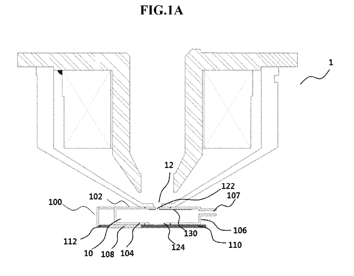
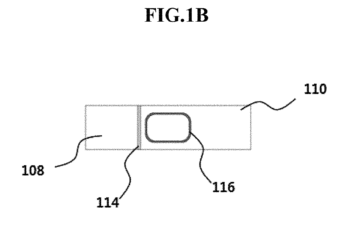
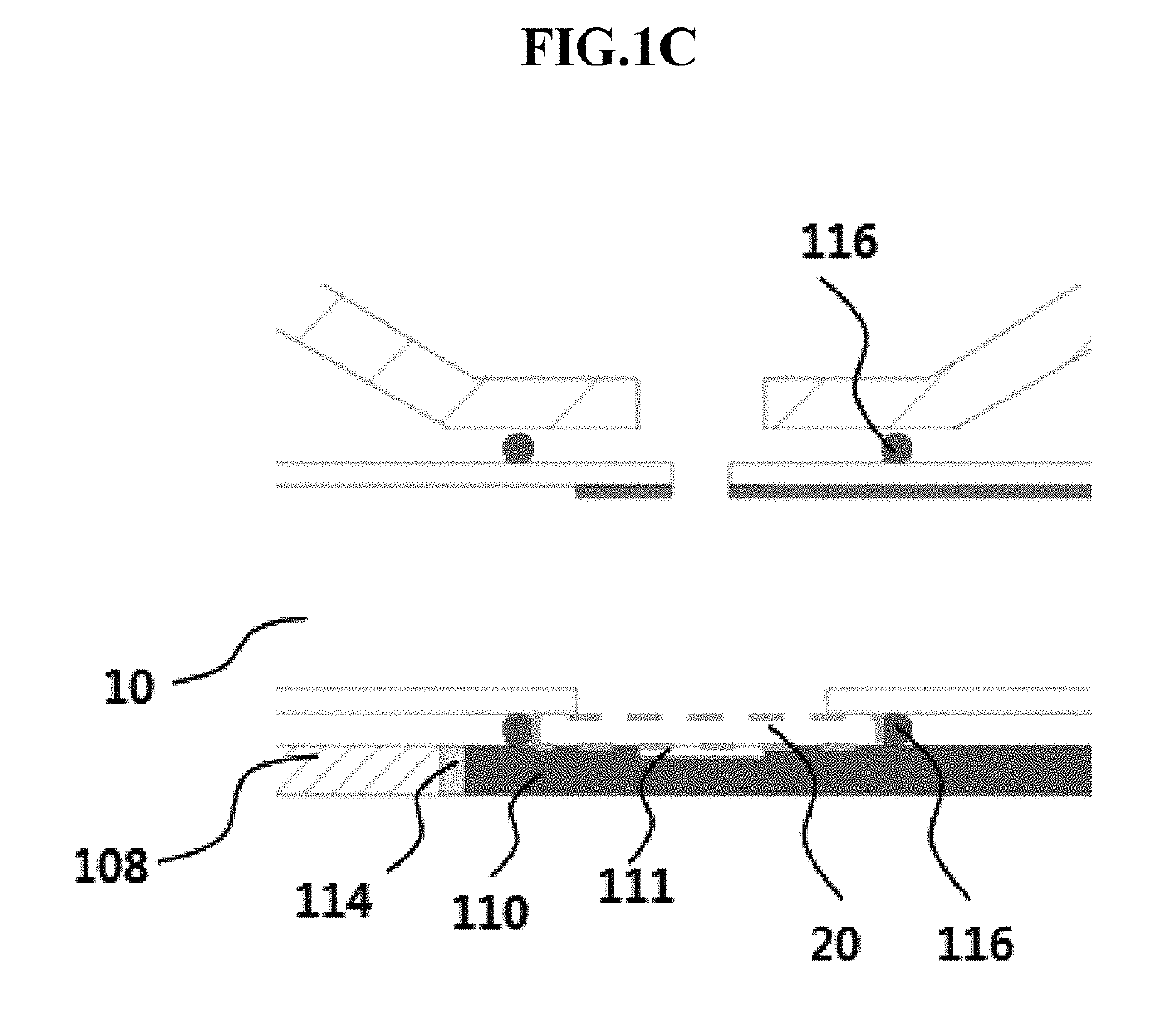
The sample chamber device described in this patent allows for easier replacement of samples while keeping the chamber in a vacuum state. This improves the efficiency of sample analysis. Additionally, the sample holder is made of transparent material, which allows for cathode luminescence and optical imaging without the need for additional equipment.

Problems solved by technology

Therefore, a structure for maintaining a vacuum state in the sample chamber becomes more complex than a sample chamber of a general electron microscope.
In the related art, however, when a sample is put into or taken out of the sample chamber, the sample chamber cannot maintain a vacuum state.
Thus, a time and cost are required until the sample chamber reaches a vacuum degree.

Method used


Image

  • Sample chamber device for electron microscope, and electron microscope comprising same
  • Sample chamber device for electron microscope, and electron microscope comprising same
  • Sample chamber device for electron microscope, and electron microscope comprising same

Examples


Embodiment Construction

[0038]Hereinafter, preferred embodiments of the present invention will be described in detail with reference to the accompanying drawings such that the present invention can easily be embodied by a person with ordinary skill in the art to which the invention pertains. Before the present invention is described in detail, the terms or words used in this specification and claims should not be limited to typical definitions or dictionary definitions. Therefore, the configurations described in this specification and the drawings are only preferred embodiments of the present invention, and do not fully represent the technical idea of the present invention. Thus, various equivalents and modifications capable of replacing the embodiments may be provided at the point of time that the present application is filed.

[0039]In one aspect, the present invention provides a sample chamber device including: a vacuum chamber having an aperture formed in a top surface portion thereof such that an electr...


PUM


Abstract

A vacuum sample chamber for a particle and optical device includes on one surface thereof, an aperture through which a particle beam to be focused along an optical axis of particles such as electrons, ions and neutral particles is incident; and on the opposite surface thereof, a detachable sample holder through which light penetrates, thereby enabling a sample to be observed and analyzed by means of the particle beam and light. A sample chamber is capable of reducing observation time by maintaining a vacuum therein even when a sample is put into or taken out from a sample chamber of an electron microscope or focused ion beam observation equipment, and capable of obtaining an optical image on the outside thereof without inserting a light source or an optical barrel into the sample chamber. A light-electron fusion microscope comprising the sample chamber.

Description

TECHNICAL FIELD[0001]The present invention relates to a sample chamber device for an electron microscope, and more particularly, to a sample chamber device for an electron microscope, which includes a sample holder detachably installed on one surface of a sample chamber, the sample holder capable of transmitting light while maintaining a vacuum state, an electron microscope including the same, and a photoelectron microscope.BACKGROUND ART[0002]A scanning electron microscope (SEM) scans a sample located in a vacuum sample chamber with a focused electron beam, and detects secondary electrons or back-scattered electrons among signals generated from the sample, thereby making it possible for a researcher to observe the target sample.[0003]Since an electron is very light, the electron bounces off a gas molecule when colliding with the gas molecule. Thus, when air is present in a body tube, the electron cannot actively move. Therefore, a high vacuum state of approximately 10−4 to 10−10 To...

Claims


Application Information

Patent Timeline
Patent Type & Authority Patents(United States)
IPC IPC(8): H01J37/16H01J37/20H01J37/244H01J37/22H01J37/26G02B21/00G02B21/02G02B21/06G02B21/36H01J37/18H01J37/285
CPCH01J37/16G02B21/02G02B21/06G02B21/36G02B21/361H01J37/18H01J37/20H01J37/226H01J37/244H01J37/26G02B21/0004H01J2237/2855H01J37/285H01J2237/166H01J2237/182H01J2237/2448H01J2237/2808H01J37/165H01J37/228H01J37/28H01J2237/2006H01J2237/204
Inventor CHO, BOK LAEAHN, SANG JUNGSUL, INHO
Owner KOREA RES INST OF STANDARDS & SCI
Learn More