
Integrative optics system, device, and method

a technology of optics and integrated optics, applied in the field of object detection systems, can solve the problems of serious performance issues in the object detection system, severely impede the ability of the radar system to detect objects, etc., and achieve the effects of reducing false positives, reducing clutter in the scene, and increasing positive predictive values

Active Publication Date: 2019-06-11
MERCURY MISSION SYST LLC
View PDF8 Cites 2 Cited by
  • Summary
  • Abstract
  • Description
  • Claims
  • Application Information

AI Technical Summary

Benefits of technology

[0006]In some embodiments, the system mitigates clutter in the scene by reducing false positives or increasing positive predictive values (PPV). Various signals may be used for target discrimination. For example, clutter signal patterns associated with known target types may be detected along with potential target signals. Additionally, specific target signals may be detected. For example, multiple retroreflections from a single ocular body may be detected, and the character of these multiple retrorefelections may be used for target discrimination.

Problems solved by technology

Clutter can cause serious performance issues in object detection systems, such as radar, LIDAR, sonar, and imaging systems.
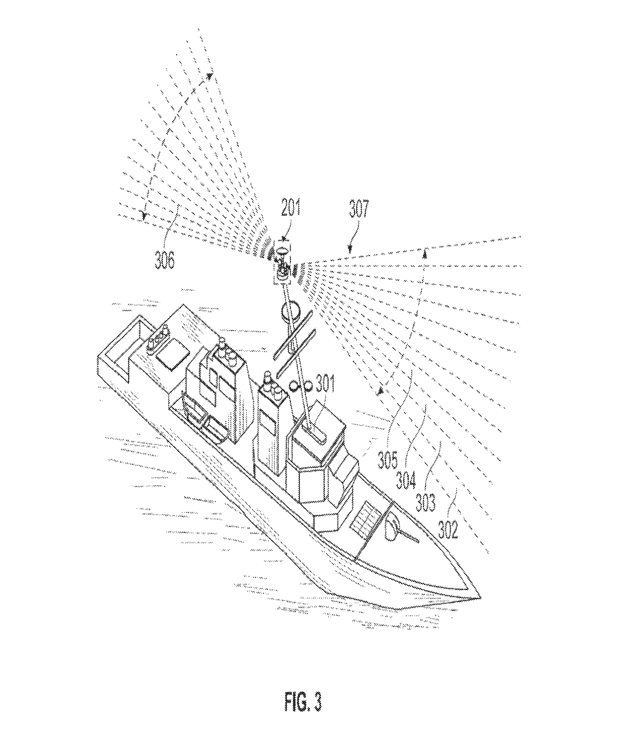
For example, in littoral environments, wave clutter can severely impede the ability of a radar system to detect objects such as periscopes.

Method used


Image

  • Integrative optics system, device, and method
  • Integrative optics system, device, and method
  • Integrative optics system, device, and method

Examples


Embodiment Construction

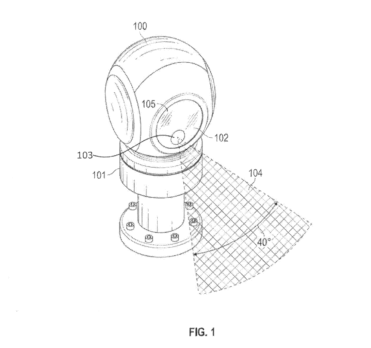
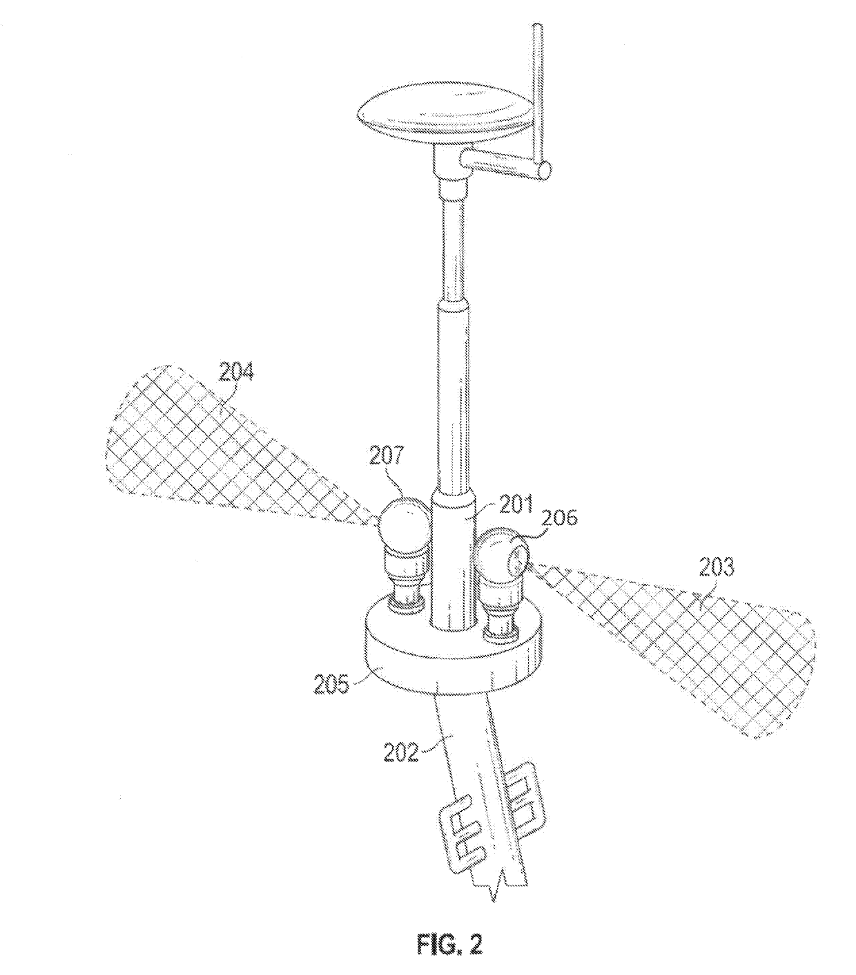
[0005]Optical detection systems are provided for detecting objects in the presence of clutter and discriminating between target objects and clutter. In some embodiments, the system is configured for detection of high brightness objects and light sources—for example, non-Lambertian reflectors, such as retroreflectors.

[0006]In some embodiments, the system mitigates clutter in the scene by reducing false positives or increasing positive predictive values (PPV). Various signals may be used for target discrimination. For example, clutter signal patterns associated with known target types may be detected along with potential target signals. Additionally, specific target signals may be detected. For example, multiple retroreflections from a single ocular body may be detected, and the character of these multiple retrorefelections may be used for target discrimination.

[0007]In various embodiments, an eye-safe laser is used to emit a diverging laser flash configured to illuminate a detection ...


PUM


Abstract

A laser is used to emit a diverging laser flash configured to illuminate a detection zone. A pseudoimaging optical receiver system is used to detect reflections from objects in the detection zone. The receiver system includes a time-gated photodetector array that is used to record signatures in a voxel array. A voxel processing module receives the voxel array and detects a reference clutter signal within the array. Potential targets are then detected according to target signals in relation to the reference clutter signal.

Description

CROSS-REFERENCE TO RELATED APPLICATIONS[0001]This application is a continuation of application Ser. No. 13 / 913,090, filed on Jun. 7, 2013, which has been assigned U.S. Pat. No. 9,689,987, issuing on Jun. 27, 2017, which claims the benefit of U.S. Provisional Application No. 61 / 659,348, filed Jun. 13, 2012; U.S. Provisional Application No. 61 / 675,256, filed Jul. 24, 2012; and U.S. Provisional Application No. 61 / 718,154, filed Oct. 24, 2012, which are hereby incorporated herein by reference in their entireties.STATEMENT OF GOVERNMENT RIGHTS[0002]One or more inventions described herein are partially supported by the following contracts for the Department of Navy under the SBIR program: M67854-10-C-6531, N00024-06-C-4121, N00014-09-C-0456, and N00014-05-C-0423. The Government may have partial rights in such inventions.TECHNICAL FIELD[0003]The present invention relates generally to object detection systems, and more particularly, some embodiments relate to systems and methods for long di...

Claims


Application Information

Patent Timeline
Patent Type & Authority Patents(United States)
IPC IPC(8): G01S17/66
CPCG01S17/66G01S17/89G01S7/4814G01S7/4816G01S17/18
Inventor JANNSON, TOMASZPRADHAN, RANJITKOSTRZEWSKI, ANDREW
Owner MERCURY MISSION SYST LLC
Learn More