Cooling apparatus for cooling a fluid by means of surface water
a technology of cooling apparatus and fluid, which is applied in the direction of lighting and heating apparatus, marine propulsion, vessel construction, etc., can solve the problems of inability to reproduce, kill most fouling organisms, and inactiveness, so as to reduce the anti-fouling effect of the entire apparatus, reduce the effect of fouling, and improve the anti-fouling
- Summary
- Abstract
- Description
- Claims
- Application Information
AI Technical Summary
Benefits of technology
Problems solved by technology
Method used
Image

Examples
Embodiment Construction
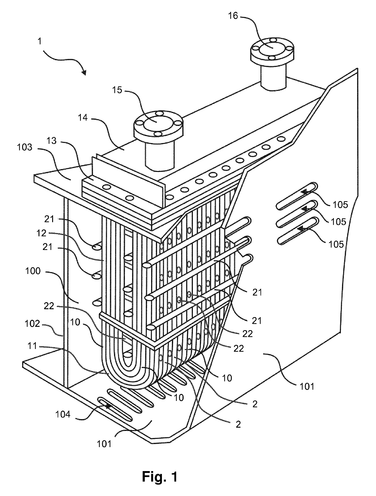
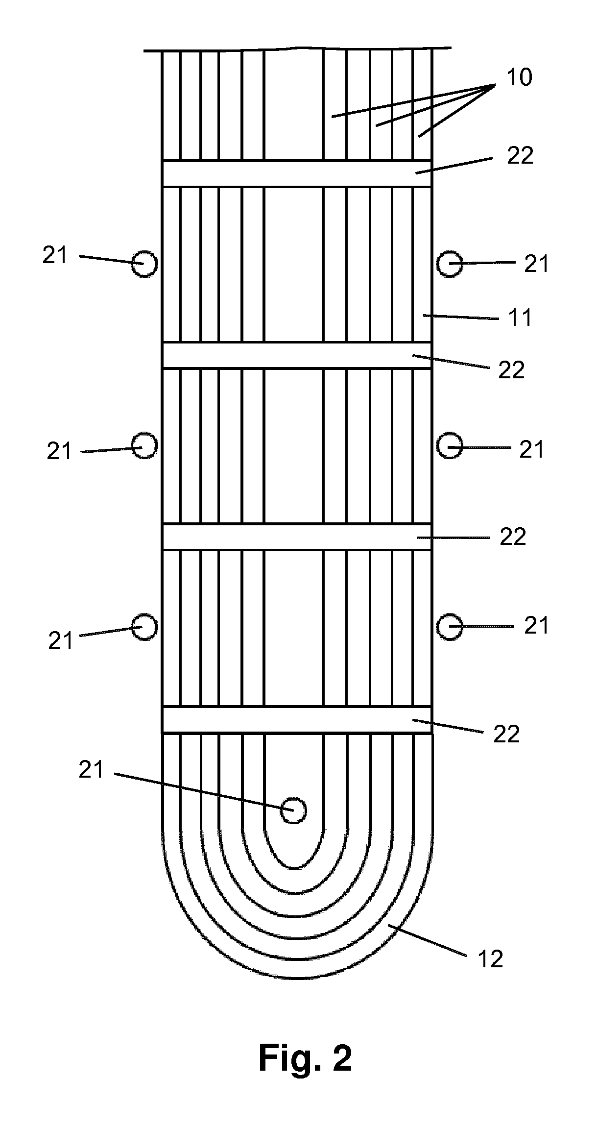
[0023]FIG. 1 shows an embodiment of the cooling apparatus according to the invention, which will hereinafter be referred to as box cooler 1. The box cooler 1 comprises a plurality of tubes 10 for containing and transporting a fluid to be cooled in their interior. The box cooler 1 is intended to be used in an engine-driven ship, wherein the fluid to be cooled is fluid from an engine cooling system of the ship, and wherein the box cooler 1 is enabled to perform its function of cooling the fluid by exposing the tubes 10 of the box cooler 1 to water from the immediate outside environment of the ship, which will hereinafter be referred to as seawater. In particular, the tubes 10 of the box cooler 1 are accommodated inside a compartment 100 of the ship, the compartment being delimited by a portion of the ship's hull 101 and a number of partition plates 102, 103. In the ship's hull 101, a number of entry openings 104 are arranged for allowing seawater to enter the compartment 100 from the ...
PUM
| Property | Measurement | Unit |
|---|---|---|
| power | aaaaa | aaaaa |
| power | aaaaa | aaaaa |
| wavelength | aaaaa | aaaaa |
Abstract
Description
Claims
Application Information