Identifying schematic and topological properties of an electrical grid through analysis of directional relationships of electrical currents

a technology of directional relationships and topological properties, applied in the field of electrical distribution, to achieve the effect of ensuring efficiency and effectiveness, and accurately determining the schematic and topological properties of the electrical grid

Inactive Publication Date: 2019-06-25
ELINTRIX
View PDF5 Cites 20 Cited by
  • Summary
  • Abstract
  • Description
  • Claims
  • Application Information

AI Technical Summary

Benefits of technology

[0016]An advantage of the invention is that it provides a technique for efficiently and accurately determining electrical-grid schematic and topological properties, identifying and reporting electrical and infrastructure events, and making this information available in useful formats, such as databases, maps and / or tables. Schematic and topological awareness provides a variety of benefits, such as, but not limited to enabling optimizations essential to “smart grid” operations; maintenance of uninterrupted power; informed decision-making, allowing assessment of contemplated, operational scenarios; near-real-time identification and localization of distribution failures; making possible the best use of resources in performing maintenance; and ensuring efficiency and effectiveness in the execution of post-disaster service-restoration.
[0017]The foregoing, and other features and advantages of the invention, will be apparent from the following, more particular description of the preferred embodiments of the invention, the accompanying drawings, and the claims.

Problems solved by technology

This is in contrast to prior art systems that rely on the measurement of signal strength, an approach that does not take best advantage of information in the signal because it fails to consider polarity of instantaneous voltages, reflective of the direction of current flow, or the intra-bus and inter-bus ingress / egress current-relationships.

Method used


Image

  • Identifying schematic and topological properties of an electrical grid through analysis of directional relationships of electrical currents
  • Identifying schematic and topological properties of an electrical grid through analysis of directional relationships of electrical currents
  • Identifying schematic and topological properties of an electrical grid through analysis of directional relationships of electrical currents

Examples


Embodiment Construction

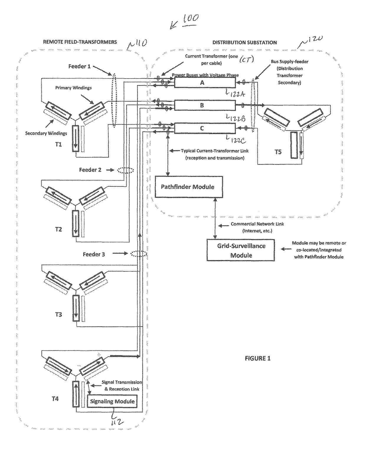
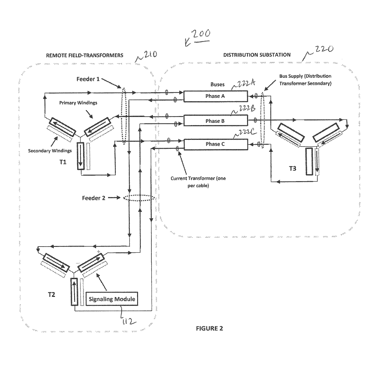
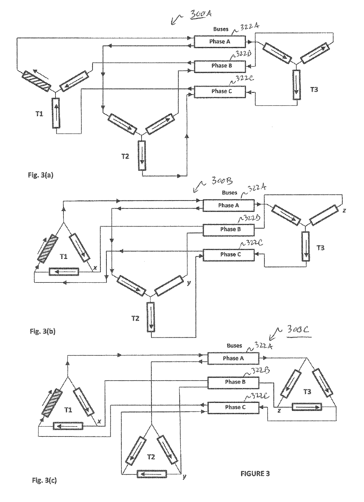
[0022]Preferred embodiments of the present invention and their advantages may be understood by referring to FIGS. 1-3, wherein like reference numerals refer to like elements. Although the present invention is described in the context of an electric or power grid, one of ordinary skill in the art readily appreciates that the concepts described herein can be applied to any type of electricity supply, or signaling, network distributing electrical power, or signals.

[0023]The current invention recognizes that “crosstalk” and “reflections” are not the cause of signals and messages appearing on feeders other than the one on which the signal was transmitted as taught in the prior art. Rather, the signals are correctly attributable to the natural flow of signal current though other conductors that complete paths back to an originating transformer-winding. The present invention leverages this insight to result in a more robust and reliable method of determining which feeder-phase(s) is / are th...


PUM


Abstract

The present invention provides an improved method of identifying which electrical conductor is supplying a signaling-point that is located on that conductor, in the electrical grid. The present invention makes the identification by measuring currents flowing into and out of a common connection-point, such as a power bus, and analyzing concurrent portions of these currents to determine whether they are ingress-current or egress-current over the analysis-intervals, and by a subsequent intra-bus and inter-bus analysis of the ingress/egress patterns. This is in contrast to prior art systems that rely on the measurement of signal strength, an approach that does not take best advantage of information in the signal because it fails to consider polarity of instantaneous voltages, reflective of the direction of current flow, or the intra-bus and inter-bus ingress/egress current-relationships.

Description

CROSS-REFERENCE TO RELATED APPLICATIONS[0001]This application claims priority under 35 U.S.C. § 119(e) to U.S. Provisional Patent Application No. 62 / 133,878, filed Mar. 16, 2015, the entire disclosure of which is incorporated by reference herein.BACKGROUND OF THE INVENTION1. Field of Invention[0002]This invention relates to electricity distribution and more particularly to a method and system for identifying schematic and topological properties of an electrical grid.2. Description of Related Art[0003]An electrical grid (or electric grid) is a network of synchronized power providers and consumers that are connected by distribution lines and operated by one or more control centers (or grid operators). Optimal operation of an electrical grid, particularly one that is geographically extensive, requires maintaining near real-time knowledge of the electrical schematic and geographic route (topology) of the distribution lines. Large grids, such as those employed by electrical utilities and...

Claims


Application Information

Patent Timeline
Patent Type & Authority Patents(United States)
IPC IPC(8): G01R19/14H02J3/00G01V3/08H02J13/00
CPCG01V3/08H02J3/00H02J13/0013G01R19/14G01R19/2513G06Q50/06H02J3/26Y02E40/50
Inventor BARNETT, ALAN DREWREED, JOSEPH ROBERT
Owner ELINTRIX
Why Eureka
Try Eureka