Eureka AIR delivers breakthrough ideas for toughest innovation challenges, trusted by R&D personnel around the world.

Method of controlling a lithographic apparatus and device manufacturing method, control system for a lithographic apparatus and lithographic apparatus

a technology of lithographic apparatus and manufacturing method, which is applied in the direction of optical devices, instruments, photomechanical devices, etc., can solve the problems of alignment errors and alignment deformation of alignment marks, and achieve the effect of eliminating or reducing over- or under-correction errors and improving overlay performan

Active Publication Date: 2019-06-25
ASML NETHERLANDS BV
View PDF12 Cites 4 Cited by
  • Summary
  • Abstract
  • Description
  • Claims
  • Application Information

AI Technical Summary

Benefits of technology

[0011]The present invention aims to improve overlay performance in lithographic processes. One aim is to eliminate or reduce the over- or under-correction of errors that results from correlation between the substrate model and the process model in known methods. Another aim is to integrate into one method different types of corrections and optimizations that have been implemented in isolation up to now.
[0031]The model mapping is a mathematical mapping between a parameter space of the substrate model and a parameter space used by the lithographic apparatus for controlling the patterning. By comparing the historical performance data and the historical alignment data, a model mapping can be established that reduces the problems identified above.

Problems solved by technology

The cause for these errors often lies in other processing steps, like CMP (chemical and mechanical polishing) and etching, which cause a deformation of the alignment marks.
This deformation of the mark results in alignment errors that vary from wafer to wafer, when alignment measurements are made in the lithographic apparatus prior to patterning.

Method used


Image

  • Method of controlling a lithographic apparatus and device manufacturing method, control system for a lithographic apparatus and lithographic apparatus
  • Method of controlling a lithographic apparatus and device manufacturing method, control system for a lithographic apparatus and lithographic apparatus
  • Method of controlling a lithographic apparatus and device manufacturing method, control system for a lithographic apparatus and lithographic apparatus

Examples


Embodiment Construction

[0045]Before describing embodiments of the invention in detail, it is instructive to present an example environment in which embodiments of the present invention may be implemented.

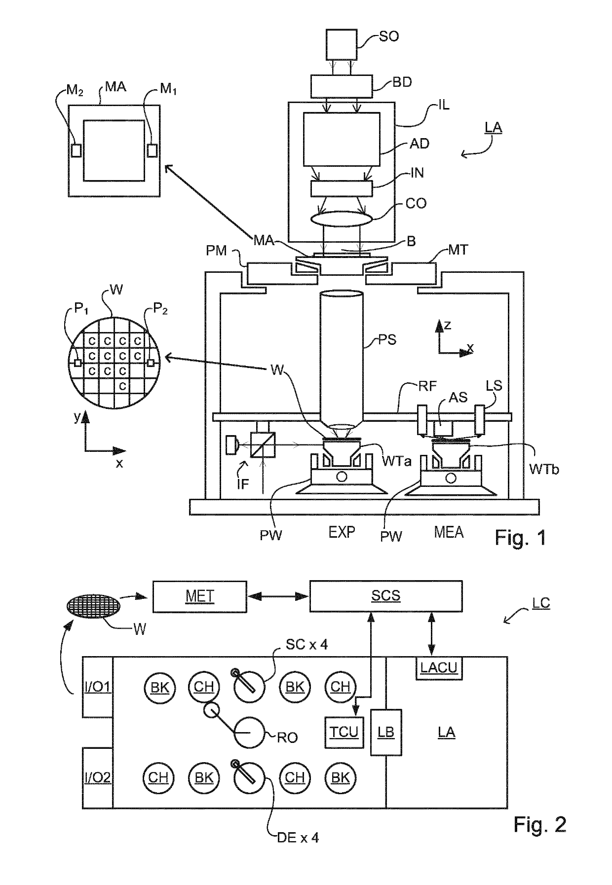
[0046]FIG. 1 schematically depicts a lithographic apparatus LA. The apparatus includes an illumination system (illuminator) IL configured to condition a radiation beam B (e.g., UV radiation or DUV radiation), a patterning device support or support structure (e.g., a mask table) MT constructed to support a patterning device (e.g., a mask) MA and connected to a first positioner PM configured to accurately position the patterning device in accordance with certain parameters; two substrate tables (e.g., a wafer table) WTa and WTb each constructed to hold a substrate (e.g., a resist coated wafer) W and each connected to a second positioner PW configured to accurately position the substrate in accordance with certain parameters; and a projection system (e.g., a refractive projection lens system) PS configured t...


PUM

PropertyMeasurementUnit
degrees of freedomaaaaaaaaaa

Abstract

In a method of controlling a lithographic apparatus, historical performance measurements are used to calculate a process model relating to a lithographic process. Current positions of a plurality of alignment marks provided on a current substrate are measured and used to calculate a substrate model relating to a current substrate. Additionally, historical position measurements obtained at the time of processing the prior substrates are used with the historical performance measurements to calculate a model mapping. The model mapping is applied to modify the substrate model. The lithographic apparatus is controlled using the process model and the modified substrate model together. Overlay performance is improved by avoiding over- or under-correction of correlated components of the process model and the substrate model. The model mapping may be a subspace mapping, and dimensionality of the model mapping may be reduced, before it is used.

Description

CROSS-REFERENCE TO RELATED APPLICATIONS[0001]This application is the U.S. national phase entry of PCT patent application no. PCT / EP2016 / 071831, which was filed on Sep. 15, 2016, which claims the benefit of priority of European patent application no. 15188943.3, which was filed on Oct. 8, 2015, and which is incorporated herein in its entirety by reference.BACKGROUND[0002]Field of the Invention[0003]The present invention relates to inspection apparatus and methods usable, for example, to perform metrology in the manufacture of devices by lithographic techniques. The invention further relates to an illumination system for use in such inspection apparatus and to methods of manufacturing devices using lithographic techniques. The invention yet further relates to computer program products for use in implementing such methods.[0004]Background Art[0005]A lithographic apparatus is a machine that applies a desired pattern onto a substrate, usually onto a target portion of the substrate. A lit...

Claims


Application Information

Patent Timeline
Patent Type & Authority Patents(United States)
IPC IPC(8): G03F7/20G03F9/00
CPCG03F7/70633G03F9/7003G03F7/705G03F9/7011
Inventor HULSEBOS, EDO MARIATINNEMANS, PATRICIUS ALOYSIUS JACOBUSBRINKHOF, RALPHHERES, PIETER JACOBLUCAS, JORN KJELDVERHEES, LOEK JOHANNES PETRUSVAN DONKELAAR, INGRID MARGARETHA ARDINABIJNEN, FRANCISCUS GODEFRIDUS CASPER
Owner ASML NETHERLANDS BV
Why Eureka
Eureka Blog
Learn More