Conductive film and touch panel sensor provided with same

a touch panel sensor and conductive film technology, applied in the direction of instruments, computing, electric digital data processing, etc., can solve the problems of easy high resistance formation, and achieve the effect of preventing the generation of a high resistance portion, eliminating or suppressing variation in electrode resistance values, and maintaining or improving the sensor sensitivity of the touch panel

Active Publication Date: 2019-06-25
FUJIFILM CORP
View PDF3 Cites 9 Cited by
  • Summary
  • Abstract
  • Description
  • Claims
  • Application Information

AI Technical Summary

Benefits of technology

[0013]In the conductive film constituted by a thin metal wire mesh, in the case of constituting an electrode using random cells, for example, a plurality of polygonal cells having different sizes, as shown in FIGS. 10A and 10B, a disconnection portion 54 is placed in thin metal wires 40 forming cells 46 of a random wiring pattern 48 according to an edge line 52 of an electrode shape and a dummy electrode 102 is electrically separated from the conduction electrode to form a conduction electrode 100. Then, depending on the position of an intersection 58 (the apex of the polygon of the cell 46) of the thin metal wires 40 constituting the cells 46, disconnection occurs on the inner side of the intersection 58. Since the cell 46 having such an intersection 58 is an open cell 46, a problem in that a portion having high resistance is formed and variation occurs in electrode resistance values easily arises.
[0015]An object of the present invention is to solve the problems of the related art and to provide a conductive film capable of preventing the generation of a high resistance portion, eliminating or suppressing variation in electrode resistance values, and maintaining or improving the sensor sensitivity of a touch panel by, in an electrode formed of thin metal wires in which the number of intersections of thin metal wires determines the resistance value, providing a disconnection portion in a thin metal wire on an edge line of a preset electrode shape and in the case in which, when a preset electrode region is provided, a flexible region (extended edge line) having a predetermined width is set on the outer side of the edge line in designing, an intersection is present in the range of the flexible region, and the entire cell is included in the inner side of the extended edge line to form a closed cell, leaving the closed cell as it as by connecting the intersection to the electrode region in designing without providing a disconnection portion in the thin metal wire on the edge line, and an electrostatic capacitive type touch panel sensor provided with the same.
[0039]As described above, according to the present invention, it is possible to prevent the generation of a high resistance portion, eliminate or suppress variation in electrode resistance values, and maintaining or improving the sensor sensitivity of a touch panel by, in an electrode formed of thin metal wires in which the number of intersections of thin metal wires constituting a closed cell determines the resistance value, providing a disconnection portion in the thin metal wire on an edge line of an electrode shape preset (in designing), and in the case in which, when an electrode area (region) preset (in designing) is provided, an extended edge line is set on the outer side of the edge line in designing, a flexible area (region) having a predetermined width is set, an intersection is present in the range of the area the entire cell is included in the inner side of the extended edge line to form a closed cell, leaving the close cell as it is by connecting the intersection to the electrode area in designing without providing a disconnection portion in the thin metal wire on the edge line.

Problems solved by technology

Since the cell 46 having such an intersection 58 is an open cell 46, a problem in that a portion having high resistance is formed and variation occurs in electrode resistance values easily arises.

Method used


Image

  • Conductive film and touch panel sensor provided with same
  • Conductive film and touch panel sensor provided with same
  • Conductive film and touch panel sensor provided with same

Examples


example 1

[0179]For Example 1, as shown in FIG. 9, ten conductive points (terminals) X1 to X10 were provided in a strip-like conduction electrode 90 at equal intervals so as to traverse the conduction electrode, and the conduction electrode 90 were divided into nine regions X1-X2, X2-X3, X3-X4, X4-X5, X5-X6, X6-X7, X7-X8, X8-X9, and X9-X10. The resistances between the points in each of the regions X1-X2 to X9-X10 were measured by a resistance meter. The measured results are shown in Table 1.

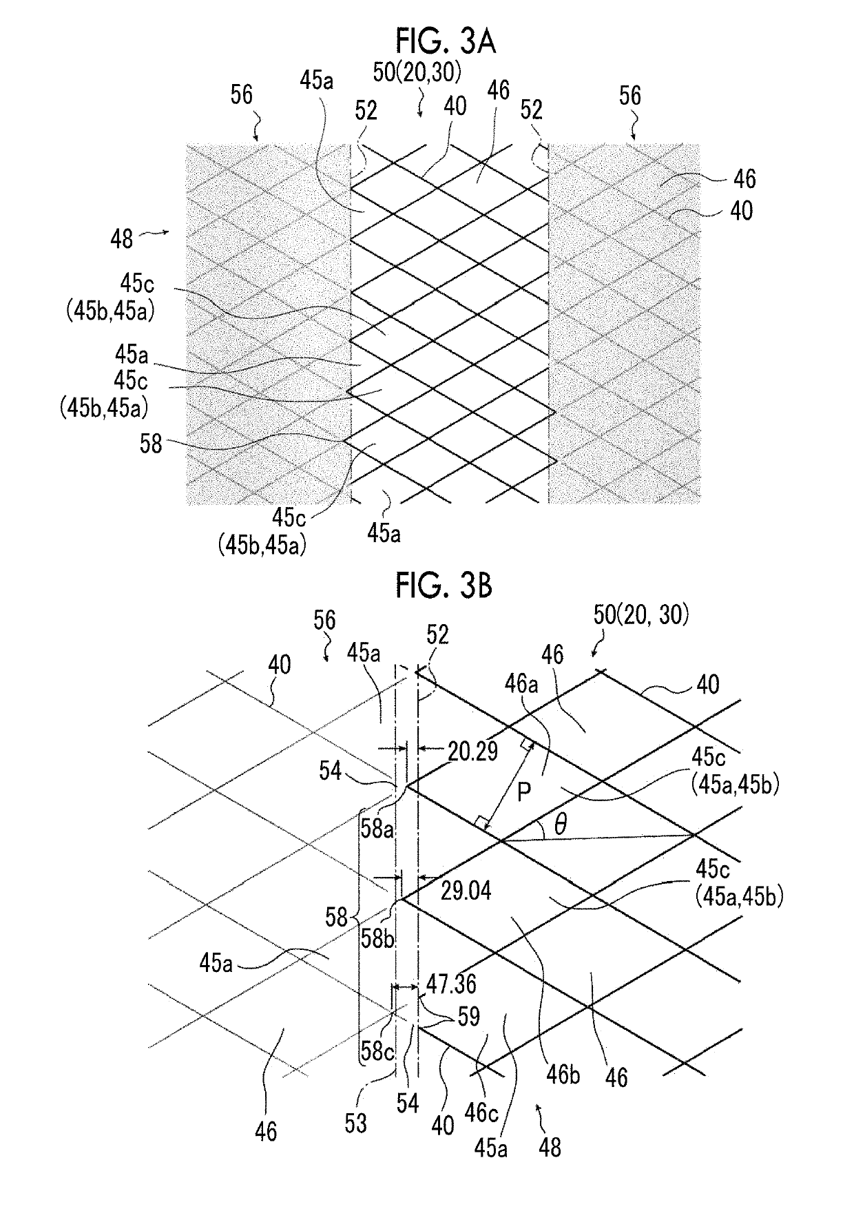
[0180]In the random electrode pattern of the conduction electrode of Example 1, randomness within ±10% was imparted to the rhombic pitch P of a regular mesh electrode pattern in which the pitch P of the cell 46 of the rhombic mesh was 352 μm, the inclined angle θ of one side of the rhombic cell 46 was 30°, and the amount of protrusion in the conduction electrode 90 of Example 1 was set to 30 μm. In addition, the electrode width of the strip-like conduction electrode 90 was 5 mm.


PUM


Abstract

A conductive film is configured such that a plurality of first cells constituted by thin metal wires crossing each edge line on both sides of a preset electrode shape of a conduction electrode extending in one direction have a disconnection portion at a position where the thin metal wires and the edge lines cross one another with the exception of a plurality of third cells in a closed state of which the number proportion is 50% or more of a plurality of second cells in which all apexes constituting a cell on an inner side of an extended edge line separated by a fixed distance from the edge line to an outer side, and the apexes of the plurality of third cells present between the adjacent edge line and extended edge line are end points, or the thin metal wires extending from the apex directly to the extended edge line have a disconnection portion.

Description

CROSS-REFERENCE TO RELATED APPLICATIONS[0001]This application is a Continuation of PCT International Application No. PCT / JP2015 / 074826 filed on Sep. 1, 2015, which claims priority under 35 U.S.C. § 119(a) to Japanese Patent Application No. 2014-240369 filed on Nov. 27, 2014. Each of the above application(s) is hereby expressly incorporated by reference, in its entirety, into the present application.BACKGROUND OF THE INVENTION[0002]1. Field of the Invention[0003]The present invention relates to a conductive film and a touch panel sensor provided with the same. Specifically, the present invention relates to a conductive film in which at least one of two electrode patterns constituted by combining a plurality of cells formed of a plurality of thin metal wires is a random pattern constituted by cells with irregularity, and a touch panel sensor provided with the same.[0004]2. Description of the Related Art[0005]Conventionally, a touch panel sensor of an electrostatic capacitive type or t...

Claims


Application Information

Patent Timeline
Patent Type & Authority Patents(United States)
IPC IPC(8): G06F3/044G06F3/0354
CPCG06F3/03545G06F3/044G06F2203/04112G06F3/0412G06F3/0445G06F3/0446
Inventor NAKAMURA, HIROSHIGE
Owner FUJIFILM CORP
Why Eureka
Try Eureka