Charging/discharging station, in particular for a battery-operated vehicle

a technology for charging/discharging stations and electric vehicles, which is applied in the direction of charging stations, electric vehicle charging technology, transportation and packaging, etc., and can solve problems such as health risks and safety problems, loss increase, and efficiency reduction

Active Publication Date: 2019-07-02
ROBERT BOSCH GMBH
View PDF10 Cites 4 Cited by
  • Summary
  • Abstract
  • Description
  • Claims
  • Application Information

AI Technical Summary

Benefits of technology

[0013]According to one embodiment, the charging / discharging station has a plurality of parking spaces, each parking space being assigned at least one such camera device. This makes it possible to exactly monitor a plurality of parking spaces. Alternatively, and for reasons of costs, a plurality of parking spaces can preferably be monitored by means of common camera devices, culminating in precisely one centrally arranged camera for all parking spaces.
[0028]The invention provides, in particular, a new method for positioning the coils, which allows a particularly low positioning tolerance. The vehicle is precisely navigated to a parking space, with the result that its secondary coil has only a small offset with respect to a primary coil assigned to the parking space. The proposed system is robust and maintenance-free, simple, fast and reliable.
[0029]In particular, no additional costs arise for the vehicle since a central camera device is used in the charging station. Since recourse is also had to a camera used in the parking positioning system, no further installation space is required for sensors in the vehicle.

Problems solved by technology

With an increasing offset between the coils, the losses increase and the efficiency is reduced.
In addition, a strong stray field, a field which emits freely and is not caught by a receiving coil, that is to say the secondary coil, may result in health risks and safety problems.
A central challenge with inductive charging is therefore that of positioning the primary coil and the secondary coil in an optimum manner with respect to one another.

Method used


Image

  • Charging/discharging station, in particular for a battery-operated vehicle
  • Charging/discharging station, in particular for a battery-operated vehicle
  • Charging/discharging station, in particular for a battery-operated vehicle

Examples


Embodiment Construction

[0038]In the following description of the exemplary embodiments of the invention, identical or similar components are denoted using identical or similar reference symbols, in which case a repeated description of these components is dispensed with in individual cases. The figures only schematically illustrate the subject matter of the invention.

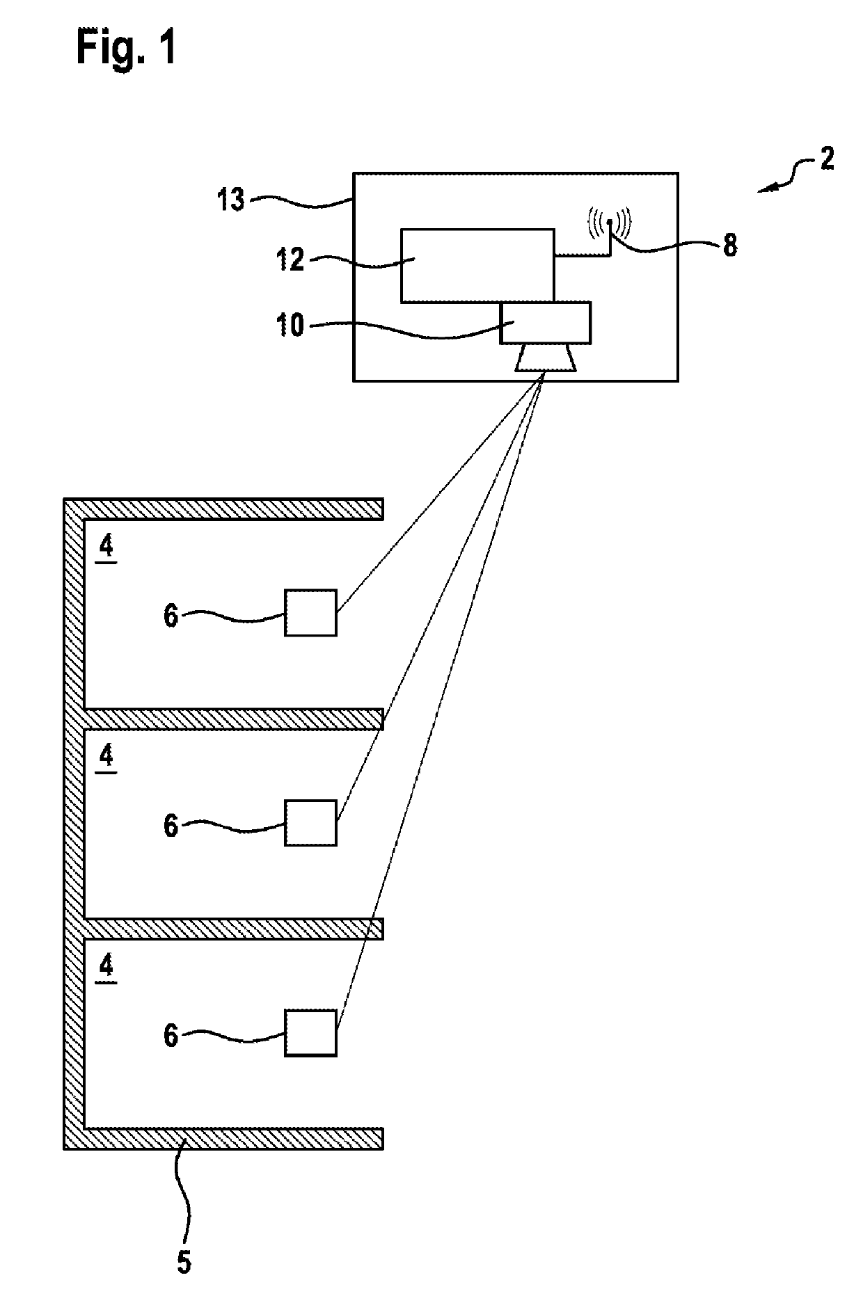
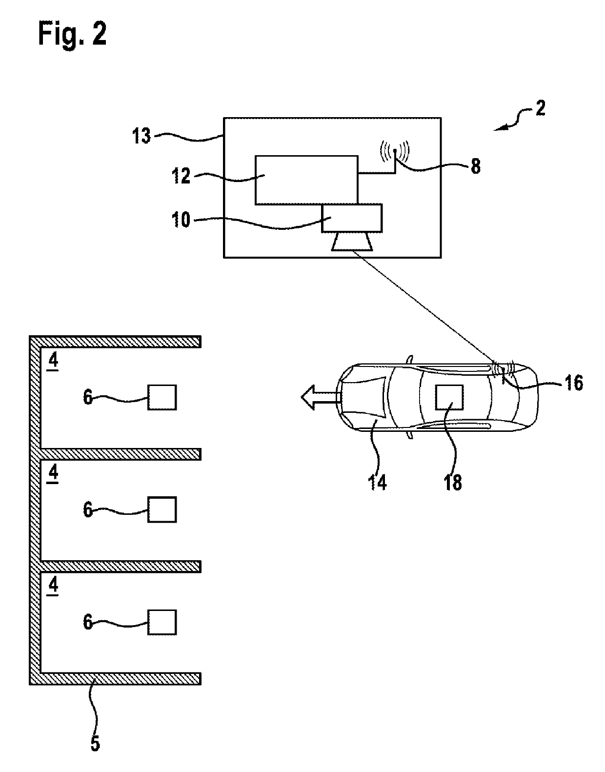
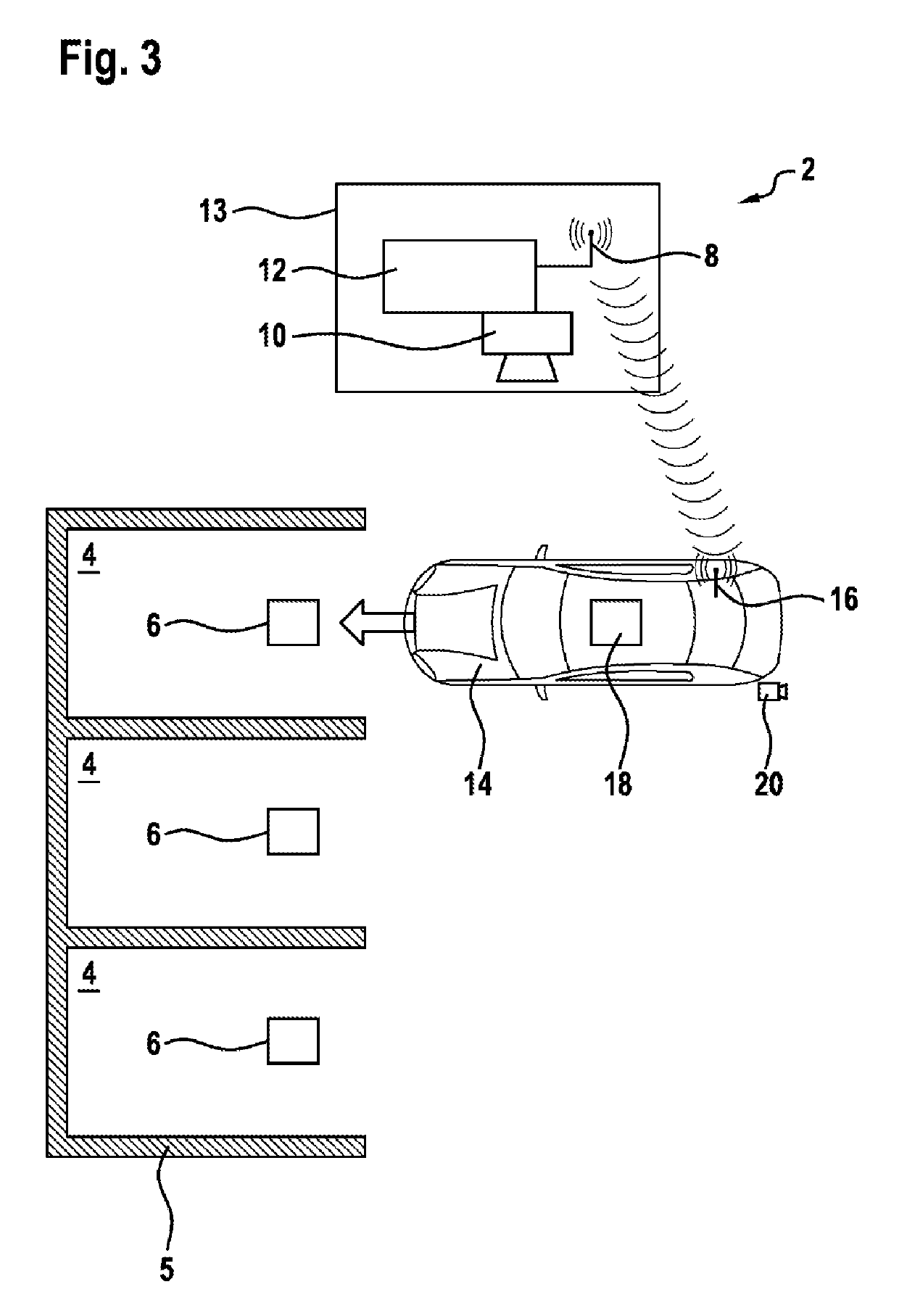
[0039]FIG. 1 shows charging / discharging station 2 according to one embodiment of the invention.

[0040]In this exemplary embodiment, the charging / discharging station 2 has three parking spaces 4, each of which is assigned a primary coil 6. The three parking spaces 4 are delimited from one another by means of boundary elements 5, in which case these may be in the form of markings on the ground, for example.

[0041]The primary coils 6 are embedded in the ground, for example, or are installed in a charging plate arranged above the ground, depending on the underlying system.

[0042]The charging / discharging station 2 also comprises a first communication ...


PUM


Abstract

The invention relates to a charging / discharging station (2) for charging or discharging an at least partly battery-operated vehicle (14) via an inductively coupled pair of coils. The charging / discharging station (2) comprises in particular a computer device (12), in which spatial coordinates of parking areas (4) are stored and which has means to navigate a vehicle (14) to the parking area (4) by means of communication units (8, 16) by using image data of the vehicle (14) recorded by means of a camera device (10) and by using physical coordinates of the parking areas (4). The invention further relates to a method for operating such a loading / discharging station (2).

Description

BACKGROUND OF THE INVENTION[0001]The invention relates to a charging / discharging station for charging or discharging an at least partially battery-operated vehicle via an inductively coupled pair of coils. A method for operating such a charging / discharging station is also provided.[0002]As an alternative to charging or discharging using a cable (so-called conductive charging), inductive charging is an innovative solution for charging or discharging at least partially battery-operated vehicles, in particular electric vehicles. Inductive charging does not require any intervention by the vehicle user, that is to say a plug does not have to be inserted in particular, and there is a certain amount of protection against weathering influences and vandalism since the relevant components, in particular a primary coil, can be inaccessibly embedded in the road surface or can be included in a charging plate placed on the road surface. The primary coil is connected to the power supply system by ...

Claims


Application Information

Patent Timeline
Patent Type & Authority Patents(United States)
IPC IPC(8): H02J7/00B60L53/39B60L53/37B60L55/00B60L53/12B60L53/30
CPCB60L53/12B60L53/37B60L53/39B60L55/00B60L53/305Y02T90/16B60L2240/62B60L2240/72Y02T10/7005Y02T10/7072Y02T90/12Y02T90/121Y02T90/122Y02T90/125Y02T90/14B60L53/126Y02T10/70
Inventor KILIC, AHMETEPPLER, STEFFEN
Owner ROBERT BOSCH GMBH
Why Eureka
Try Eureka