Method of navigating an agricultural vehicle, and an agricultural vehicle implementing the same

a technology of agricultural vehicles and odometers, applied in traffic control systems, color televisions, traffic control systems, etc., can solve the problems of difficult to measure exact turn angles of vehicles, difficult to achieve absolute positions of wheels, and less accurate, etc., to achieve the effect of improving the precision of such navigation

Active Publication Date: 2009-12-24
CLAAS E SYST GMBH
View PDF7 Cites 25 Cited by
  • Summary
  • Abstract
  • Description
  • Claims
  • Application Information

AI Technical Summary

Benefits of technology

[0013]The object of the present invention is to provide a method of navigating an agricultural vehicle that will enhance the precision of such navigation.
[0014]In accordance with the invention said method comprises: obtaining from the 3D imaging device frames imaging at least a part of the surroundings of the vehicle at different points of time while the vehicle is moving thus providing a chronological sequence of frames, analysing the frames, and establishing a change of pose of the vehicle using results of the analysis of at least two chronologically different frames. Using frames (or images or pictures) obtained from the 3D imaging device provides for high accuracy, which again provides for precise navigation.

Problems solved by technology

Wheel odometry does not give an absolute position and it drifts over time.
The turn angles for the vehicle are hard to measure exactly due to tire slip of the steering wheels.
It is however less accurate due to the physical ways it measures signals.
Radar is therefore not very usable for accurate positioning.
One drawback of the GPS system is that it requires an unobstructed view to the GPS satellites.
Typically this cannot always be guaranteed meaning the system has a tendency to fail at times. There are many sources of errors in GPS including multi-path errors and atmospheric effects.
The problem with a system of this kind is that position estimates quickly drift if the GPS signal is lost.
Also it has a long settling time before it runs stable.
The fields of use envisaged in this publication are thus remote from agriculture.
Thus valuable information about change of pose immediately prior to the most resent firewall is lost for future estimates.
This is adversely to the accuracy of the method and the reliability of its results.

Method used


Image

  • Method of navigating an agricultural vehicle, and an agricultural vehicle implementing the same
  • Method of navigating an agricultural vehicle, and an agricultural vehicle implementing the same
  • Method of navigating an agricultural vehicle, and an agricultural vehicle implementing the same

Examples


Embodiment Construction

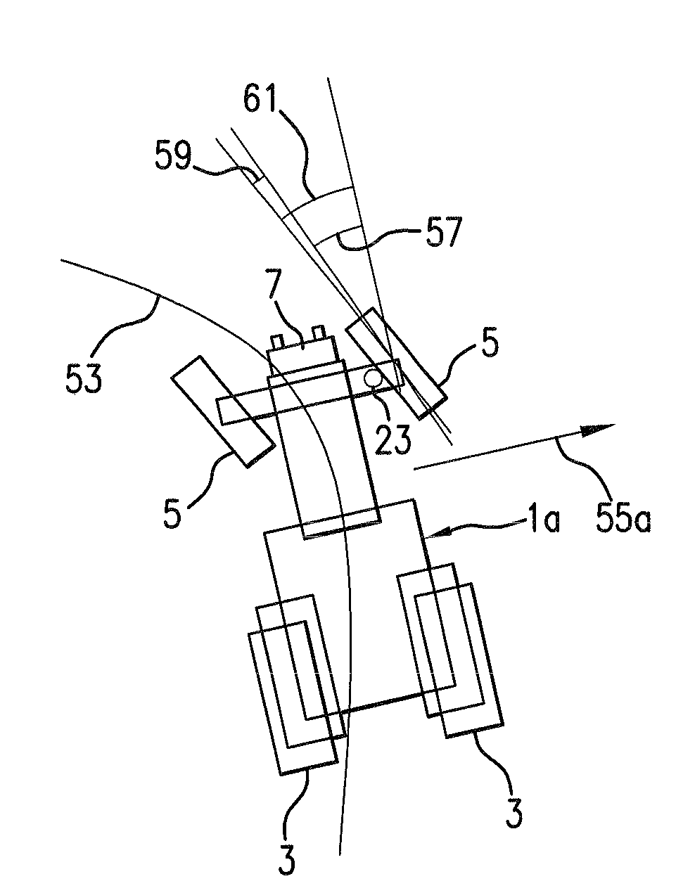
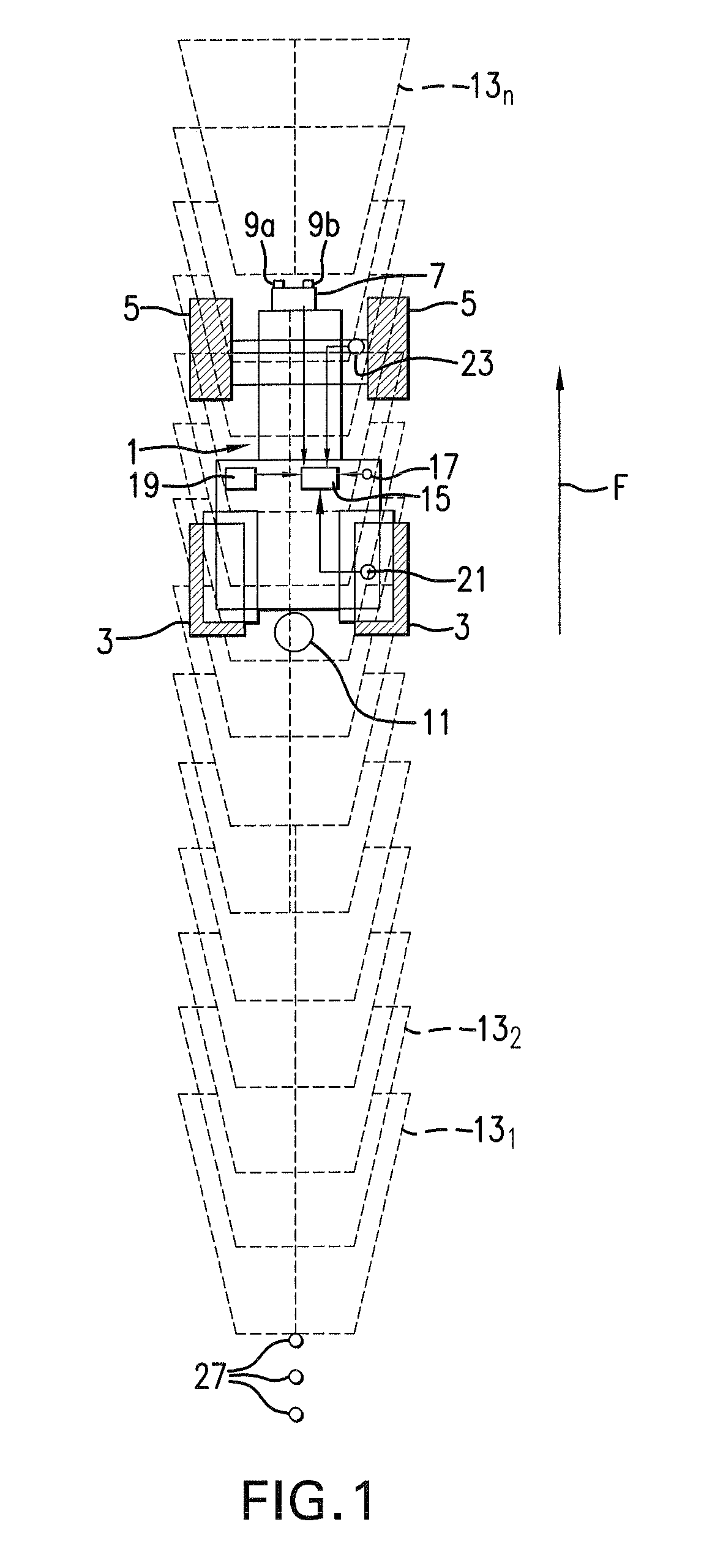
[0041]FIG. 1 shows a tractor 1 with driving wheels 3 and steering wheels 5. The tractor 1 is at the front equipped with a stereo camera 7 with two objective lenses 9a and 9b. The tractor further has a coupling point 11 for attachment of an implement. Driving in the forward further direction F the stereo camera 7 images areas 131, 132, . . . 13n of the surrounding ground in front of the tractor 1. For sake of clarity only a limited number of the imaged areas are shown. The tractor is further provided with a computer 15 for processing the images provided by the stereo camera 7. The computer comprises a memory.

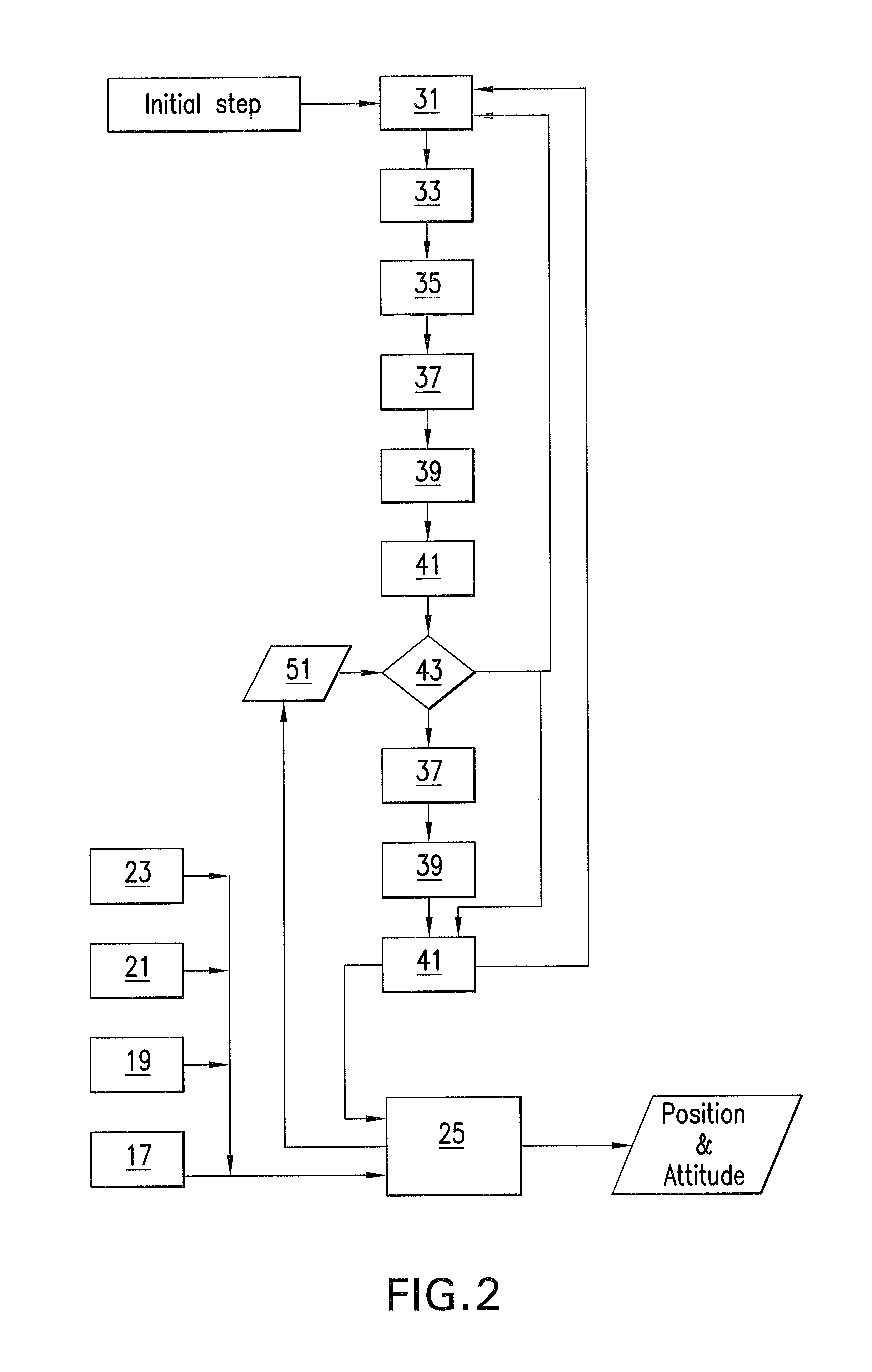
[0042]The tractor 1 is further equipped with other navigation sensors, namely: a GPS-antenna or GPS-sensor 17, an IMU-sensor 19, and a wheel odometry-sensor comprising a driving wheel encoder 21 and a steering wheel gauge 23. The computer 15 implements a prior art navigation system 25 (FIG. 2) receiving input from these navigation sensors as indicated in FIGS. 1 and 2. The naviga...


PUM


Abstract

A method of navigating an agricultural vehicle, which is equipped with a 3D imaging device for imaging surroundings of the vehicle, and an image processing device, includes obtaining from the 3D imaging device frames imaging at least a part of the surroundings of the vehicle at different points of time while the vehicle is moving thus providing a chronological sequence of frames, analysing the frames, and establishing a change of pose of the vehicle using results of the analysis of at least two chronologically different frames.

Description

CROSS-REFERENCE TO RELATED APPLICATION[0001]The invention described and claimed hereinbelow is also described in European Patent Application EP 08 158 693.5 filed on Jun. 20, 2008. This European Patent Application, whose subject matter is incorporated here by reference, provides the basis for a chain of priority of invention under 35 U.S.C. 119(a)-(d).BACKGROUND OF THE INVENTION[0002]The present invention relates to a method of navigating an agricultural vehicle, said vehicle being equipped with a 3D imaging device for imaging surroundings of the vehicle, and an image processing device.[0003]Within agriculture it is a wish to be able to measure or establish the speed, the position, the heading etc. of a vehicle in order to be able to navigate the vehicle and any implement attached thereto in an agricultural field.[0004]Methods and devices currently used in navigating agricultural vehicles comprise:[0005]Wheel odometry, which uses encoders to measure how many revolutions the wheels h...

Claims


Application Information

Patent Timeline
Patent Type & Authority Applications(United States)
IPC IPC(8): G01C21/00
CPCA01B69/001
Inventor MADSEN, TOMMY ERTBOLLEMORTEN, RUFUS BLAS
Owner CLAAS E SYST GMBH
Why Eureka
Try Eureka