Method and device for carrying out an integrity test on a filter element

a filter element and integrity test technology, applied in the direction of liquid/fluent solid measurement, volume metering, instruments, etc., can solve the problems of filter element wetting with alcohol, method temperature dependent, and lasting approximately 8 hours

Active Publication Date: 2019-07-16
SARTORIUS STEDIM BIOTECH GMBH
View PDF16 Cites 6 Cited by
  • Summary
  • Abstract
  • Description
  • Claims
  • Application Information

AI Technical Summary

Benefits of technology

[0048]The method steps can be carried out, chronologically staggered, at three different test stations each having one filter element to be tested. In this case the method step at one test station can always be reclocked synchronously with the method steps at the two other test stations, wherein the most time-critical method step in each case with the longest process time is the clock generator for reclocking of the method steps. Thus in each process phase it is ensured that only one single line to the respective vessel is opened, namely the line which is associated with the respective method step. This can be ensured, for example, by the use of controllable three-way valves, for example, by use of Robolux valves, by means of which in each case one of three different conduits can be connected to the vessel. As a result, on each vessel a fast reclocking, virtually free of dead spaces, between the method steps is ensured. Furthermore, interactions between the test stations can be avoided.
[0054]The device can have, instead of one single line, for example, a filling conduit for filling of the vessel as well as a compacting conduit for setting the pressure of the fluid in the vessel. In this case the filling conduit can be connected, for example, to a source of RO water by means of which RO water can be introduced into the filling conduit. The filling of the vessel can take place from the bottom upwards, in order to enable turbulence-free filling and safe ventilation. The filling can be ended when a filling level sensor at the outlet of an air-vent conduit makes contact with water and closes an intake by means of a valve, so that the filling conduit can again be separated from the vessel. The air-vent conduit can be fitted with a slight slope, so that it empties in the direction of the slope. This type of filling can make it possible that during the filling operation no pressure occurs above the specific (predetermined or predeterminable) test pressure.
[0058]An internal fluid feed has the advantage that no conduits have to be provided between the internal fluid feed and the vessel, since the displacement body can be formed, for example, at a location on the vessel wall so that it can be introduced and / or inserted through the vessel wall into the interior of the vessel. In this case the displacement body can be designed to be passed in a fluid-tight manner through the vessel wall.
[0067]During the compacting operation or in connection with the compacting operation a gross leak test of the first filter element can take place, for example, by means of a Coreolis mass flow sensor integrated in the compacting conduit, the measurement range of which is adapted to the compacting volume of the product group to be tested, specifically of the filter element to be tested. Furthermore, the mass flow sensor makes it possible to measure, in addition to the mass flow, the density and temperature of the fluid from the compacting vessel. If the measured value of the mass flow sensor during the compacting permanently exceeds a predetermined value, i.e. the compacting does not decrease with the time progression as expected, the filter element to be tested is evaluated as a reject with a gross leak. Subsequently a changeover from compacting to maintenance of the pressure and measurement are prevented in order to avoid unwanted emptying of the pressure measurement cell during the measurement, since otherwise the pressure measurement cell would have to be topped up again.

Problems solved by technology

Conventional methods of testing hydrophobic filter elements are either wetted with alcohol and measured at diffusion / bubble point in the single-digit minute range with the known disadvantages of subsequent drying.
This testing technology is regarded as an indirect testing method and has the disadvantages that the testing method is temperature-dependent and requires a reference volume for carrying out the measurement.
Furthermore, the known method has the disadvantage that the filter element must be wetted with alcohol for the measurement.
As a result, a final drying process in explosion-proof drying cabinets is necessary, which can last for approximately 8 hours.
In order to produce a measurable pressure drop, testing times in the double-digit minute range of usually 23 minutes per testpiece are necessary, which is why the WFT method is not suitable for an industrial scale and is not suitable for testing very small filter elements.
In particular, the disadvantages of the WFT method such as, for example, the long measurement time, the limited accuracy of measurement and / or the restricted field of application should be reduced.
During compacting of the filter element, a particularly large amount of fluid can be pressed through the filter element, particularly when the filter element is damaged and thus has a reduced intrusion pressure.
Often 23 or more minutes pass before the occurrence of the continuous volume flow, which (as described in the introduction) leads to long testing times. In the method, however, the determination of the integrity characteristic variable takes place substantially earlier, i.e. already while the volume flow is still changing.
It usually takes a long time until a continuous volume flow occurs.

Method used


Image

  • Method and device for carrying out an integrity test on a filter element
  • Method and device for carrying out an integrity test on a filter element
  • Method and device for carrying out an integrity test on a filter element

Examples


Embodiment Construction

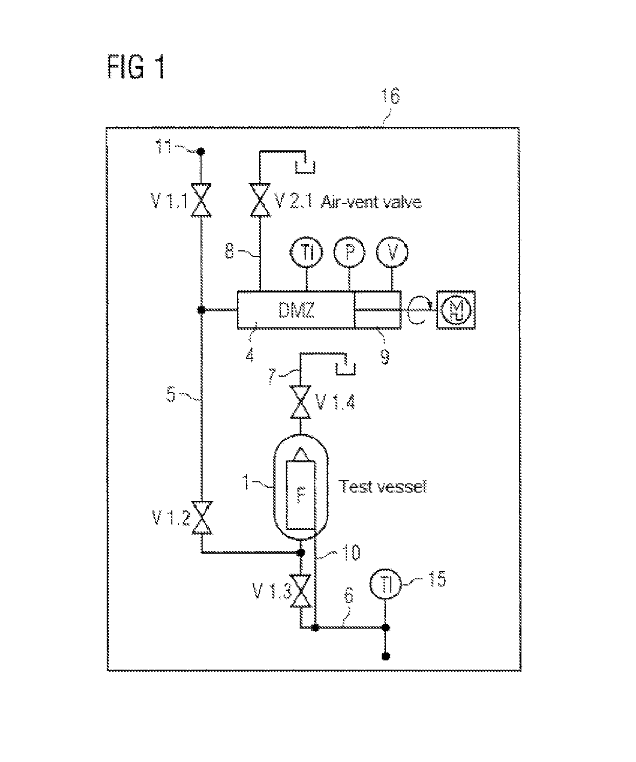
[0078]FIG. 1 shows a schematic representation of a device 16 for carrying out an integrity test on a filter element. The integrity of a filter element F arranged in a vessel 1 is checked by the device.

[0079]The device 16 is connected to a fluid inflow 11. The fluid inflow 11 is adjustable by means of a fluid inlet valve V1.1. A fluid can be introduced into a fluid conduit 5 via the fluid inflow 11. In this case RO water is preferably used as the fluid.

[0080]The fluid conduit 5 is connected to a pressure measurement cell (DMZ) 4 as a special configuration of a fluid feed. Furthermore, the fluid conduit 5 can be connected by means of a vessel valve V1.2 to the vessel 1.

[0081]The pressure measurement cell 4 can be connected to an evaluation means, which may for example be in the form of a PC. The pressure measurement cell 4 can be controlled by means of the evaluation means, in particular a pressure measurement cell controller 9 (as a special configuration of a fluid feed controller or...


PUM

PropertyMeasurementUnit
volumeaaaaaaaaaa
pressureaaaaaaaaaa
internal volumeaaaaaaaaaa

Abstract

A method for carrying out an integrity test on a filter element includes filling a fluid into at least one vessel (1), in which a filter element (F) to be tested is arranged. The method proceeds by setting the pressure of the fluid in the vessel (1) to a predetermined test pressure, and maintaining the test pressure in the vessel (1) with controlled replenishment of fluid into the vessel (1) and / or a controlled change in internal volume of the vessel (1). The method continues by determining an integrity characteristic variable for the filter element (F) in a manner dependent on the controlled replenishment of fluid into the vessel (1) and / or dependent on the controlled change in internal volume of the vessel (1) before attaining a substantially continuous volume flow of fluid for maintaining the specific test pressure in the vessel (1).

Description

BACKGROUND[0001]1. Field of the Invention[0002]The present invention relates to a method and a device for testing the integrity of filter elements, in particular filter elements for sterile filtration.[0003]2. Description of the Related Art[0004]Filtration systems for sterile filtration of gases and liquids are employed in many areas of technology, in particular in the pharmaceutical industry, food production, the electronics industry etc. Sterile filters with membranes made of different polymers are employed for sterile filtration. In the sterile filtration of gases and in the sterile ventilation from vessels, in particular in the pharmaceutical industry, standard sterile filters with hydrophobic membranes such as, for example, membranes based on polytetrafluoroethylene (abbreviated to PTFE) are employed.[0005]Conventional methods of testing hydrophobic filter elements are either wetted with alcohol and measured at diffusion / bubble point in the single-digit minute range with the kn...

Claims


Application Information

Patent Timeline
Patent Type & Authority Patents(United States)
IPC IPC(8): B01D65/10G01F15/12B01D71/36G01N15/08
CPCB01D71/36G01N15/0826B01D65/102G01F15/125G01N2015/086G01N2015/084
Inventor ARMGART, DIETERLEISER, DIRKRAKEBRANDT, VANESSAVAN DEN BOOGAARD, JUERGEN
Owner SARTORIUS STEDIM BIOTECH GMBH
Why Eureka
Try Eureka