
Efficient organic electroluminescent devices with red fluorescent dopants

a technology of fluorescent dopants and organic electroluminescent devices, which is applied in the direction of discharge tube luminescnet screens, natural mineral layered products, etc., can solve the problems of high resistance of the medium, the problem of most problematic research for a primary red light, and the operation of the el device requires a relatively high voltage (>100 volts) to achieve the effect of improving luminous efficiency and chromaticity

Inactive Publication Date: 2005-01-04
E RAY OPTOELECTRONICS TECH
View PDF2 Cites 7 Cited by
  • Summary
  • Abstract
  • Description
  • Claims
  • Application Information

AI Technical Summary

Benefits of technology

This invention replaces the four methyl groups of DCJTR with five strategically positioned aliphatic or aromatic groups with the intention to alleviate the fluorescence-quenching problem of the dye at high concentration. It is expected that the interaction between molecules of the dye will be lessened due to the enhanced steric interaction that may reduce the propensity for dye aggregation at high concentration.
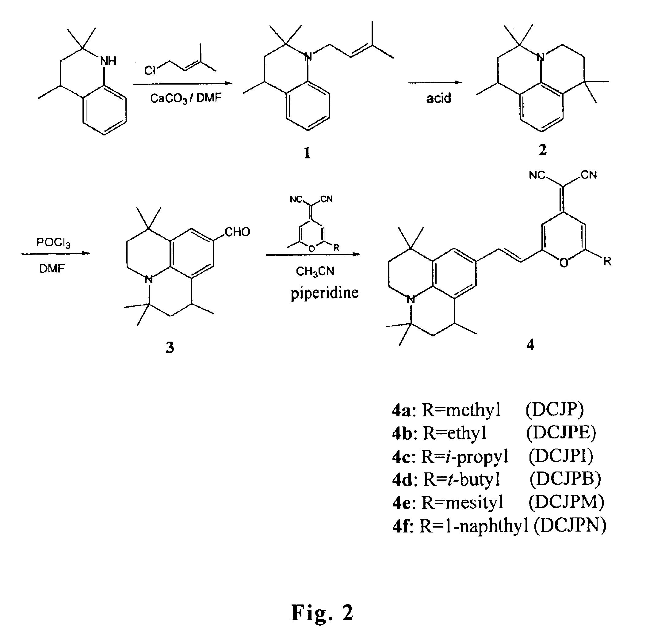
The red fluorescent dopants, 4-(dicyanomethylene)-2-R6-(1,3,3,7,7-penta-methyljulolidyl-9-enyl)-4H-pyran (DCJPR, Formula 1) series of compounds, according to the present invention are prepared by a new reaction route that is different from and better than that of DCJTR. In particular, the yield of the intermediate pentamethyljulolidine of DCJPR of the present invention is significantly higher than that of the intermediate tetramethyljulolidine of DCJTR. As a result, the overall reaction yield of DCJPR is far better than that of DCJTR thereby offers the advantage of producing the red dopant more cost effective.
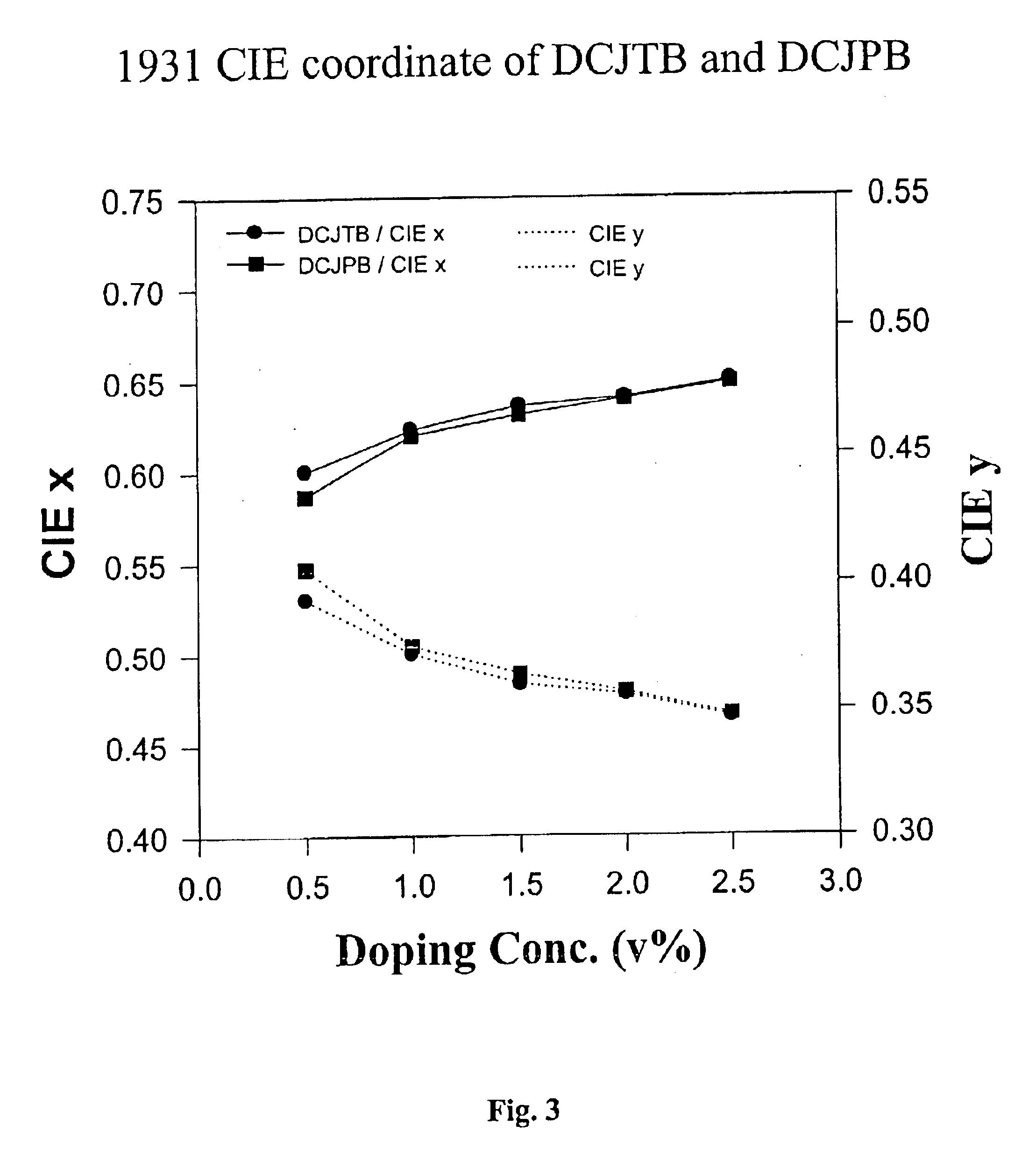
When compared under similar doping concentrations, it was found that the new dopant DCJPB (Formula 1, R=t-Bu) offers higher luminance yield than that of DCJTB at the similar chromaticity. In addition, DCJPB having a lower melting point than that of DCJTB is easier to purify by train sublimation without incurring thermal-induced decomposition.
It is a feature of the present invention that when the compound is applied to EL devices it provides a fluorescent compound devoid of chemical reactivity of the extra “active” methyl group, thereby avoiding the formation of the unwanted bis-condensed dye in the reaction product mixture. Moreover, in the properties of organic EL devices under the same doping concentrations, DCJPB has a thermal stability similar to DCJTB, but a better luminous efficiency and an almost same chromaticity.

Problems solved by technology

Thus, this organic EL medium was highly resistive and the EL device required a relatively high voltage (>100 volts) to operate.
Among the three primary colors of lights, the research for a primary red light is most problematic.
This is because the red guest dyes aggregate and influence each other at high concentrations, which leads to the quenching of the luminescence.
In the aforementioned patent, the preparation and subsequent purification of both DCM and DCJ are complicated by the inevitable generation of significant amount of an unwanted corresponding bis-condensed dye caused by the further reaction of the “active” methyl group present in the fluorescent dye molecules (see Hammond, Optics Comm., 1989, 29, 331).
Furthermore, once the bis-condensed dye is formed in the reaction mixture, it is difficult to be removed and tends to diminish or extinguish DCM (or DCJ) fluorescence.
Thereby, the methyl groups result in a steric hindrance between dye molecules, and thus reduce the quenching effect caused by the formation of aggregate due to high concentration.
While DCJT has a good luminance efficiency, the controlling of synthesis and purification remains a problem.
Therefore, the preparation and subsequent purification of DCJT are also complicated by the inevitable generation of significant amount of the unwanted bis-condensed dye that tends to decrease the fluorescence efficiency of DCJT.
However, the red EL devices produced by doping the main EL emitter with DCJTB have some drawbacks.
The main disadvantage is that the required doping concentration of DCJTB is up to 24% if the hue of light emission is to be tuned to the CIE red position in standard displays.
In particular, among most of the current OLED RGB primary colors, the luminance efficiency of red light is poor.
In addition, the yield of the key intermediate tetramethyljulolidine in the synthesis of DCJTR is low.

Method used


Image

  • Efficient organic electroluminescent devices with red fluorescent dopants
  • Efficient organic electroluminescent devices with red fluorescent dopants
  • Efficient organic electroluminescent devices with red fluorescent dopants

Examples


example 1

Synthesis of Compound 4a (DCJP)

Synthesis of Compound 1

23.5 g of 1-chloro-3-methyl-butene and 28 g of calcium carbonate was added to a solution of 28 g of 2,2,4-trimethyl-1,2,3,4-tetrahydroquinoline (the detailed synthesis of 2,2,4-trimethyl-1,2,3,4-tetrahydroquinoline can be found in U.S. Pat. No. 3,247,211) in 200 mL of DMF. The reaction mixture was stirred at room temperature for 3 hours. The reaction mixture was then extracted with diethyl ether and water. The organic layer obtained was dried over MgSO4, concentrated and purified by chromatography using ethyl acetate / hexane (1 / 8) as the eluent to give 36.7 g of brown liquid. Yield: 94%.

Synthesis of Compound 2

A solution of 25 g of compound 1 in 200 mL of concentrated sulfuric acid was stirred at room temperature for 4 hours. The mixture was poured onto pieces of ice, neutralized with an ammonium hydroxide aqueous solution and then extracted with diethyl ether. The organic layer obtained was dried over MgSO4, concentrated and purif...

example 2

Synthesis of Compound 4b (DCJPE)

A solution containing 20 g of compound 3, 0.1 g of piperidine, 13.7 g of 2-(2-ethyl-6-methyl-4H-4-pyranyliden) malononitrile and 250 mL of acetonitrile was stirred at 45° C. for 4 hours. The mixture was diluted with water and then extracted with diethyl ether. The organic layer obtained was dried over MgSO4, concentrated and purified by passing through a silica gel column using ethyl acetate / hexane (1 / 7) as the eluent to give 25.9 g of red solid. Yield: 80%. Mp: 276° C.

example 3

Synthesis of Compound 4c (DCJPI)

A solution containing 18.5 g of compound 3, 0.1 g of piperidine, 13.6 g of 2-(2-isopropyl-6-methyl-4H-4-pyranyliden) malononitrile (the synthesis procedure was reported by Chen et al. Thin Solid Films 363, 327, 2000) and 250 mL of acetonitrile was stirred at 45° C. for 5 hours. The mixture was diluted with water and then extracted with diethyl ether. The organic layer obtained was dried over MgSO4, concentrated and purified by passing through a silica gel column using ethyl acetate / hexane (1 / 7) as the eluent to give 25.9 g of red solid. Yield: 84%. Mp: 269° C.


PUM

PropertyMeasurementUnit
Nanoscale particle sizeaaaaaaaaaa

Abstract

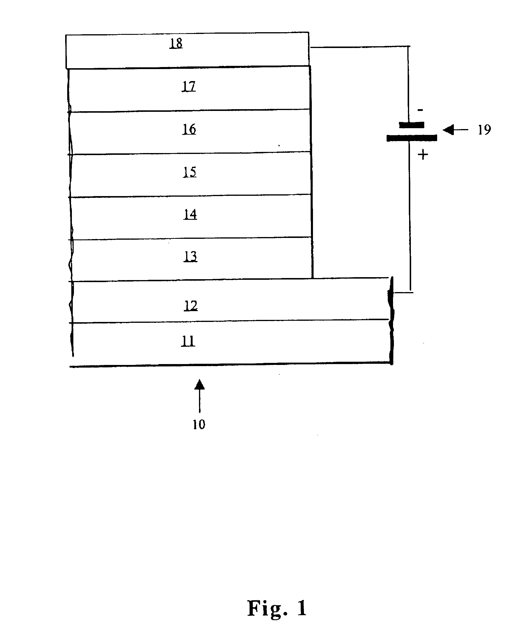
An organic electroluminescent (EL) device (10) in accordance with the present invention comprises, in sequence, a glass substrate (11), an anode layer (12), a hole-injecting layer (13), a hole-transporting layer (14), an luminescent layer (15), an electron-transporting layer (16), an electron-injecting layer (17) and a cathode layer (18). The luminescent layer (15) is doped with a guest fluorescent doping material, and the guest fluorescent doping material for the luminescent layer (15) comprises a compound represented by Formula I: wherein R1, R2, R3, R4, R5, and R6 each independently represents a linear or branched aliphatic group having from 1 to 10 carbon atoms or an aromatic group having from 5 to 20 carbon atoms.

Description

FIELD OF THE INVENTIONThe present invention relates to organic electroluminescent (EL) devices and more specifically to organic EL devices comprising red fluorescent dopants.BACKGROUND OF THE INVENTIONOrganic EL devices are known to be highly efficient and are capable of producing a wide range of colors. Useful applications such as flat-panel displays have been contemplated and commercialization is well underway. Representative of earlier organic EL devices are Gurnee et al., U.S. Pat. No. 3,172,862, issued Mar. 9, 1965; Gurnee, U.S. Pat. No. 3,173,050, issued Mar. 9, 1965; Dresner, “Double Injection Electroluminescence in Anthracene,”RCA Review, Vol. 30, pp. 322-334, 1969; and Dresner, U.S. Pat. No. 3,710,167, issued Jan. 9, 1973. Typical organic emitting materials were formed of a conjugated organic host material and a conjugated organic activating agent having condensed benzene rings. The organic emitting material was present as a single layer medium having a thickness much above...

Claims


Application Information

Patent Timeline
IPC IPC(8): C09K11/06H01L51/05H01L51/30H05B33/14H01L51/50H01L51/00
CPCC09K11/06H01L51/0065H05B33/14Y10S428/917H01L51/0037H01L51/0059H01L51/006H01L51/0067H01L51/0077H01L51/0078H01L51/0081H01L51/0092H01L51/5012H01L51/5048H01L51/5088H01L2251/308C09K2211/1033H10K85/1135H10K85/653H10K85/631H10K85/654H10K85/633H10K85/311H10K85/30H10K85/381H10K85/324H10K50/11H10K50/14H10K50/17H10K2102/103
Inventor HUANG, WEN-YAOCHANG, MIN-JONGHUANG, WEN-CHIN
Owner E RAY OPTOELECTRONICS TECH
Learn More