
Optically initiated configuration and cryptographic test key transfer for testing interconnected electronic devices

a technology of cryptographic test key and interconnected electronic devices, applied in the field of logic analysis and analytic components, can solve the problems of inaccuracy or unusability of electronic communications, numerous defective communication sources, electronic noise being communicated into a transmitted electronic signal or gaps forming in the signal

Inactive Publication Date: 2019-07-16
WEBSTER DAVID
View PDF3 Cites 0 Cited by
  • Summary
  • Abstract
  • Description
  • Claims
  • Application Information

AI Technical Summary

Benefits of technology

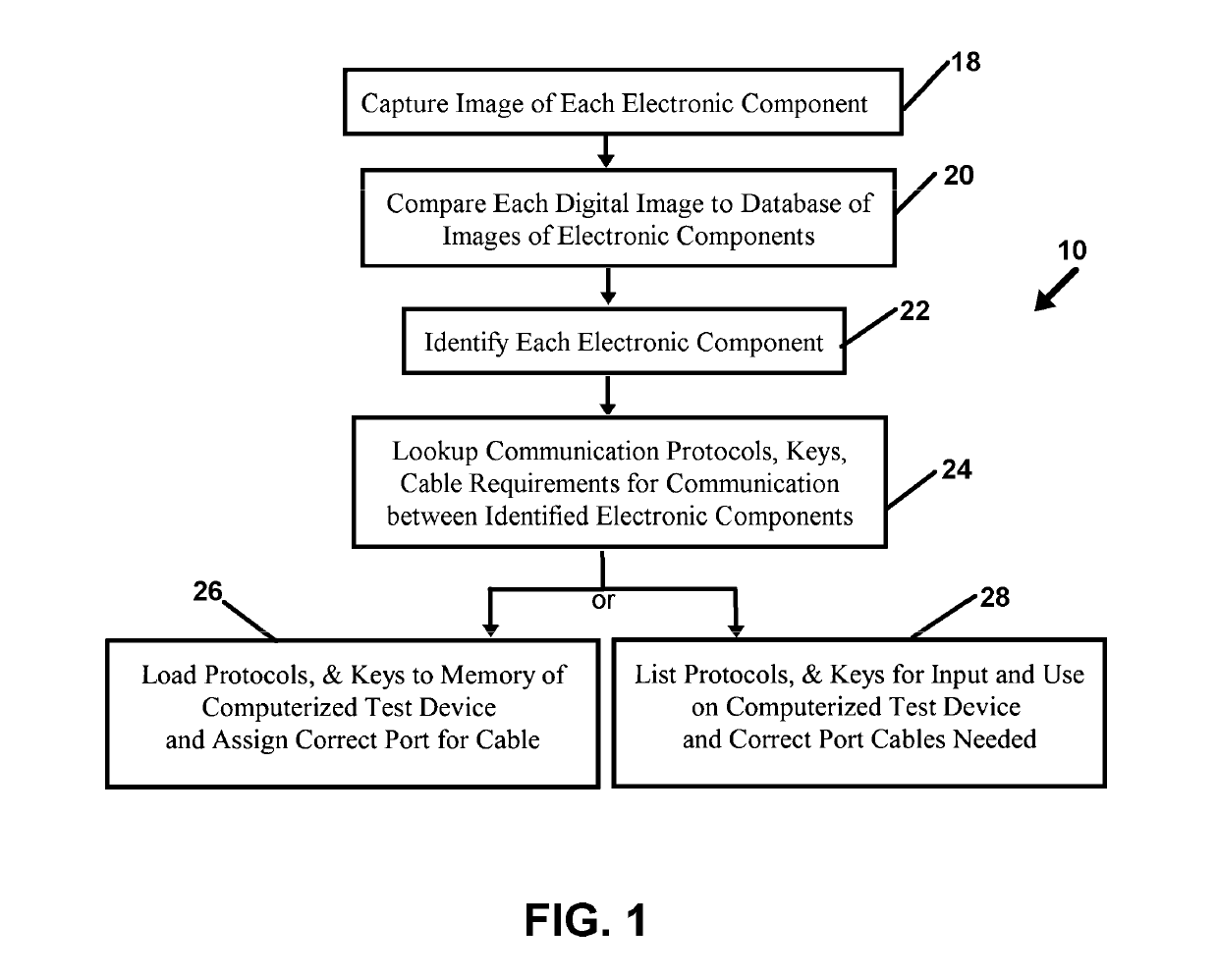
The present invention is a system that uses digital photo recognition to identify electronic components and their communications interface. The system employs software and a database of electronic devices to provide the user with required information for connecting the components. The system can discern the device identity of each electronic component and provide the necessary communications protocols, connections, and keys for testing the components. The system can also provide the user with information about the cables, wireless frequencies, and electronic communication protocols required for connecting the components. The invention allows for easy testing of electronic communications between components and provides a convenient way to connect components in a portable pad or laptop. The invention is not limited to the specific details provided and can be applied in different ways.

Problems solved by technology

Unfortunately, inaccurate or unusable electronic communications can result from numerous defective communication sources along a transmission pathway.
Such defective communications generally result in electronic noise being communicated into a transmitted electronic signal or gaps forming in the signal when received.
Such errant signals can occur due to wire breaks, or where connections have corroded, or become loose, or electronic parts are failing and for a plethora of other reasons.
Correcting this problem of an errant signal being received is a communication nightmare where the electronic signal is both in an electronic protocol more affected by noise, and / or which is encrypted in a manner where signal noise renders the electronically encrypted signal unuseable.
In testing communications over electronic channels between electronic devices, the longer the pathway the signal must follow on the communications channel, the more potential exists for electronic noise to be added to the electronic signal transmitted.
Thus, as a transmitted signal using one or more protocols propagates through a transmission medium or pathway between communicating electronics components, the longer the distance between the transmission and reception point the more potential exists for noise being imparted to the signal.
However, noise and momentary electrical disturbances such as voltage variances or frequency variances, EMF energy, and other types of electrical interference, have a high potential to cause non-continuous signal anomalies which are imparted into the signal transmitted across the channel from the source.
Such electrical anomalies can easily cause changes in the transmitted data as it passes through a communications channel which render portions unemployable during reassembly with the appropriate protocol, or yield errors in the communication on reassembly.
This of course can cause significant changes in the discerned data on the receiving end of the channel using the appropriate protocol for the transmission, thus communicating unuseable or intelligible data to the reception point.
The potential for such data transmission errors also can occur where the transmission hardware using electronic components for generating the electronic signal according to the protocol used, or with the reception hardware itself.
These malfunctions can be caused by defective components yielding errors in the signal varying from the transmission protocol employed, or the receiving electronic device can also error in discerning the incoming signal due to malfunctioning components.
For a technician attempting to ascertain a source of an electronic data communication problem where a signal reception point or device, suffers from lost or unusable data or impaired data communications on the communications channel, a problem arises.
The technician has to discern if the errant signal reception is due to electrical disturbances caused by physical defects or EMF along the pathway for the electronic signal, or whether the errant received signal is caused by the component transmitting, or whether the signal received is useable but the component receiving the electronic signal is flawed.
This can be an arduous task for the technicians to try to look up the serial numbers or other identifying indicia on each device.
This identification system is very time consuming, especially where identifying indicia on a piece of equipment has been removed or worn off.
In many cases, identifying each electronic component, and its related connections and protocols, and keys, can take longer than the test itself.
If the technician errors in any of the identifications and related requirements, the test will be invalid or unuseable, and they must redo the setup.
Various limitations of the related art will become apparent to those skilled in the art upon a reading and understanding of the specification below and the accompanying drawings.

Method used


Image

  • Optically initiated configuration and cryptographic test key transfer for testing interconnected electronic devices
  • Optically initiated configuration and cryptographic test key transfer for testing interconnected electronic devices
  • Optically initiated configuration and cryptographic test key transfer for testing interconnected electronic devices

Examples


Embodiment Construction

[0038]In this description, the directional prepositions of up, upwardly, down, downwardly, front, back, top, upper, bottom, lower, left, right and other such terms refer to the device as it is oriented and appears in the drawings and are used for convenience only; they are not intended to be limiting or to imply that the device has to be used or positioned in any particular orientation.

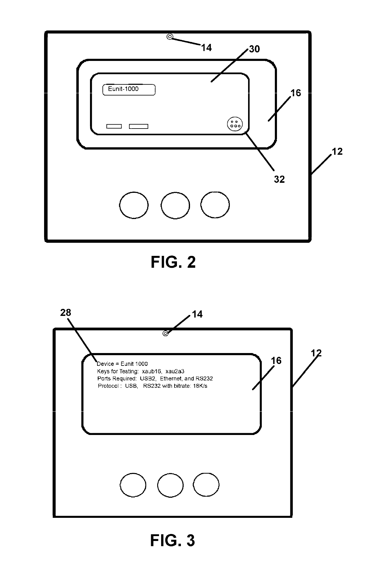
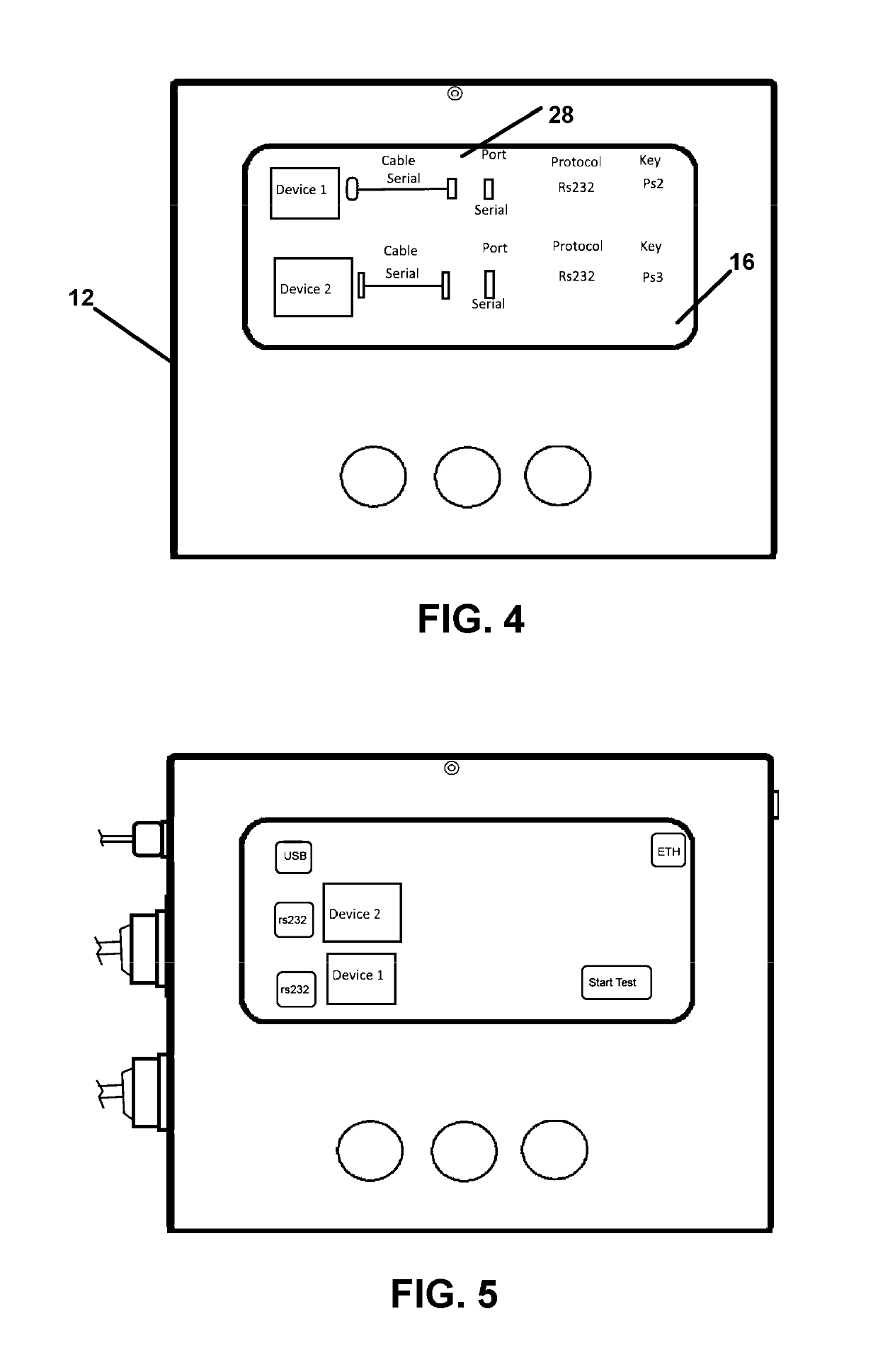
[0039]Now referring to drawings in FIGS. 1-5, there is seen in FIG. 1 a preferred flow diagram representation of the method 10 herein for optical image identification of electronic components and their communications protocols and connections, enabled by the use of a portable computing device 12 having electronic memory and an onboard digital camera 14 and a video display 16 screen shown for example in FIG. 2.

[0040]The portable computing device 12 such as a smartphone, a laptop computer or a pad computer having onboard power, a computer and electronic memory adapted for running software therein and st...


PUM


Abstract

A method identifying electronic communication components employed for transmitting and receiving electronic communications for subsequent testing thereof is provided which identifies each electronic communication component using a digital photo thereof. Communications characteristics required for communicating with each identified component are discerned using the component identity ascertained from the digital image.

Description

[0001]This application claims priority to U.S. Provisional Patent Application Ser. No. 62 / 213,557 filed on Sep. 2, 2015, which is included herein in its entirety by this reference thereto.1. FIELD OF THE INVENTION[0002]The present invention relates generally to logic analyzing and analytic components which are interfaced between multiple electronic components which send and receive electronic data using electronic signals. More particularly, the invention relates to a method and apparatus for automatically determining the proper communications protocol and interconnection requirements for communication between connected electronic devices, through the employment of optical recognition of each such component to be employed, to thereby ascertain communications protocols and security keys and data interconnections for testing communications.2. PRIOR ART[0003]Electronic communication between computers and other electronically connected communications components and systems and related t...

Claims


Application Information

Patent Timeline
Patent Type & Authority Patents(United States)
IPC IPC(8): G06K9/00G06F16/532G06F16/583G06V20/00
CPCG06F16/5838G06K9/00624G06F16/532G06K2209/03G06V20/00G06V2201/02
Inventor WEBSTER, DAVID
Owner WEBSTER DAVID
Learn More