Organic mandrel protection process

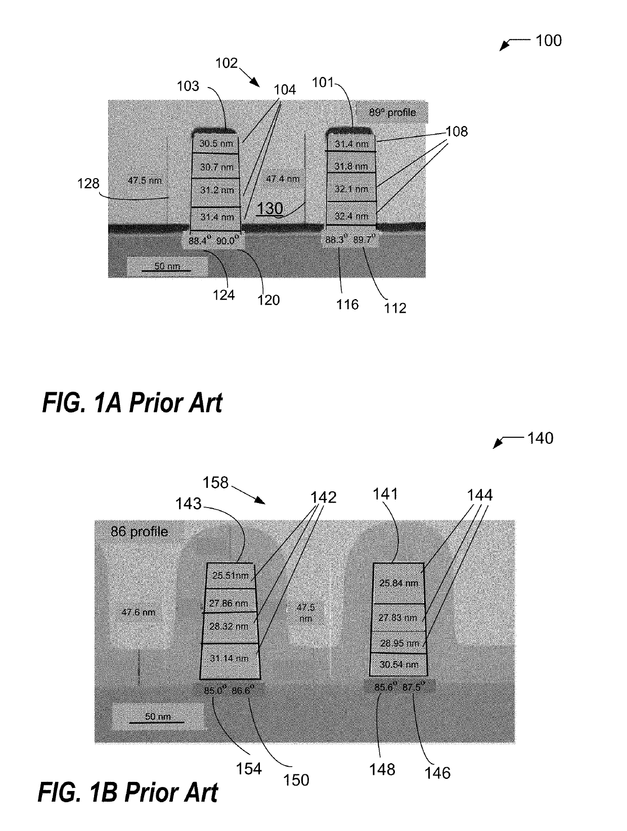
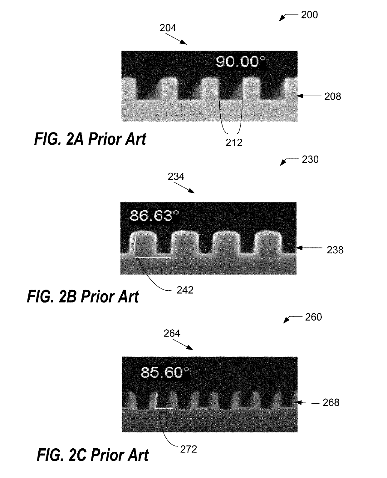
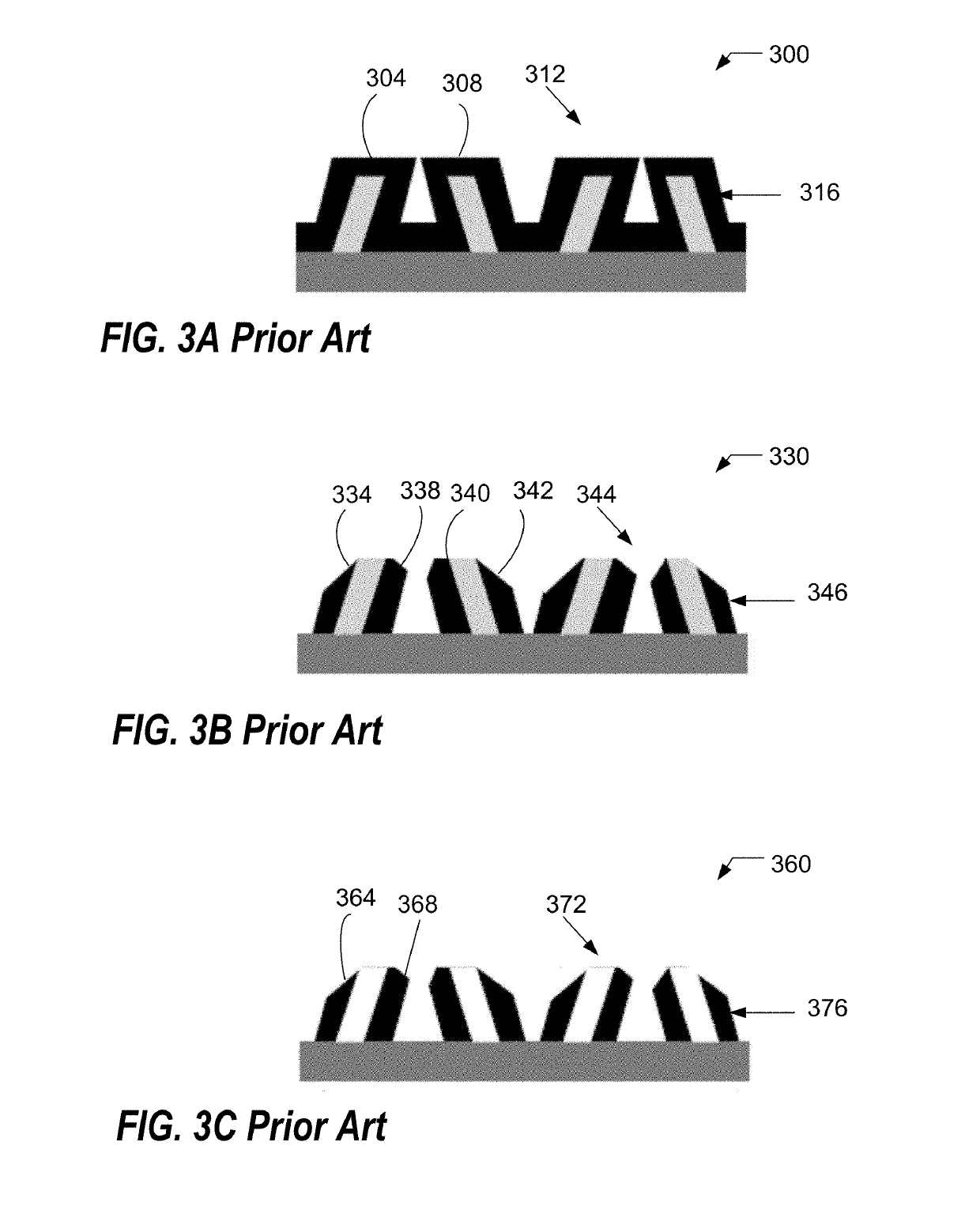
a mandrel protection and process technology, applied in the direction of electrical equipment, basic electric elements, semiconductor/solid-state device testing/measurement, etc., can solve the problems of fidelity transfer and roughness problems, negative affecting pattern fidelity and edge placement in downstream integration steps, and increasing line width roughness, line edge roughness, and edge placement error problems

Active Publication Date: 2019-07-16
TOKYO ELECTRON LTD
View PDF10 Cites 204 Cited by
  • Summary
  • Abstract
  • Description
  • Claims
  • Application Information

AI Technical Summary

Problems solved by technology

However, the initial top mandrel material loss leads to a mandrel pattern that is no longer rectangular, i.e., with a perfect square top but to a trapezoidal shape with the top of the mandrel being smaller than the bottom of the mandrel.
This trapezoidal shape also leads to leaning spacers being deposited which negatively affect pattern fidelity and edge placement in downstream integration steps.
The leaning of the spacer and the reduction of the thickness can result in increased line width roughness, line edge roughness, and edge placement error issues.
Further pitch splitting can amplify the leaning of the spacer and damage to the spacers, resulting in fidelity transfer and roughness problems.

Method used


Image

  • Organic mandrel protection process
  • Organic mandrel protection process
  • Organic mandrel protection process

Examples


Embodiment Construction

[0028]Methods and systems for RF power distribution in a multi-zone electrode array are presented. However, one skilled in the relevant art will recognize that the various embodiments may be practiced without one or more of the specific details, or with other replacement and / or additional methods, materials, or components. In other instances, well-known structures, materials, or operations are not shown or described in detail to avoid obscuring aspects of various embodiments of the invention.

[0029]Similarly, for purposes of explanation, specific numbers, materials, and configurations are set forth in order to provide a thorough understanding of the invention. Nevertheless, the invention may be practiced without specific details. Furthermore, it is understood that the various embodiments shown in the figures are illustrative representations and are not necessarily drawn to scale. In referencing the figures, like numerals refer to like parts throughout.

[0030]Reference throughout this ...


PUM

PropertyMeasurementUnit
sidewall angleaaaaaaaaaa
voltageaaaaaaaaaa
timeaaaaaaaaaa

Abstract

Provided is a method of patterning spacers, the method comprising: providing an initial patterned structure in a substrate in a processing chamber, the initial patterned structure comprising an organic mandrel and an underlying layer; exposing the patterned structure in a direct current superposition (DCS) plasma treatment process, the process depositing a layer of a first material on the initial patterned structure; performing an atomic layer conformal deposition process using a second material, the first material providing protection to the organic mandrel at the beginning of the atomic layer conformal deposition process; performing a spacer etch mandrel pull process, the process creating a final patterned structure with a target final sidewall angle; concurrently controlling integration operating variables in the DCS plasma treatment process, the atomic layer conformal deposition process, and the spacer etch mandrel pull process in order to meet the target final sidewall angle and other integration objectives.

Description

CROSS-REFERENCE TO RELATED APPLICATIONS[0001]Pursuant to 37 C.F.R. § 1.78(a)(4), this application claims the benefit of and priority to U.S. Provisional Application No. 62 / 347,460, filed Jun. 8, 2016, and U.S. Provisional Application No. 62 / 373,500, filed Aug. 11, 2016, which is expressly incorporated by reference herein in its entirety.BACKGROUND OF THE INVENTIONField of Invention[0002]The present invention relates to systems and methods for substrate processing, and more particularly to a method and system for enhancing fidelity of pattern transfer and reducing leaning and edge placement errors of a patterned structure.Description of Related Art[0003]This invention relates to multi-patterning schemes which utilize a spacer. Multi-patterning is used in both the front end of the line and the back end of the line to target pitches that are not available through conventional 193 immersion lithography alone. Several multi-patterning schemes can be used to target the required pitch. Due...

Claims


Application Information

Patent Timeline
Patent Type & Authority Patents(United States)
IPC IPC(8): H01L21/033H01L21/66H01L21/311H01L21/027H01L21/02
CPCH01L21/0337H01L21/0228H01L21/0276H01L21/02164H01L21/02274H01L21/0335H01L21/31116H01L21/31138H01L22/12H01L22/20H01L21/0332H01L22/26
Inventor KO, AKITERURALEY, ANGELIQUETHIBAUT, SOPHIENAKAMURA, SATORUMOHANTY, NIHAR
Owner TOKYO ELECTRON LTD
Why Eureka
Try Eureka