
System for multi-region processing

a multi-region processing and screening system technology, applied in the direction of chemical vapor deposition coating, metal material coating process, coating, etc., can solve the problems of hpc processing techniques that have not been successfully adapted to hpc processing techniques, deposition methods that have not been successfully adapted to mocvd technologies, and the inability to implement a variable for rotation within each site isolated region, so as to prevent cross-contamination

Active Publication Date: 2012-12-20
INTERMOLECULAR
View PDF31 Cites 384 Cited by
  • Summary
  • Abstract
  • Description
  • Claims
  • Application Information

AI Technical Summary

Benefits of technology

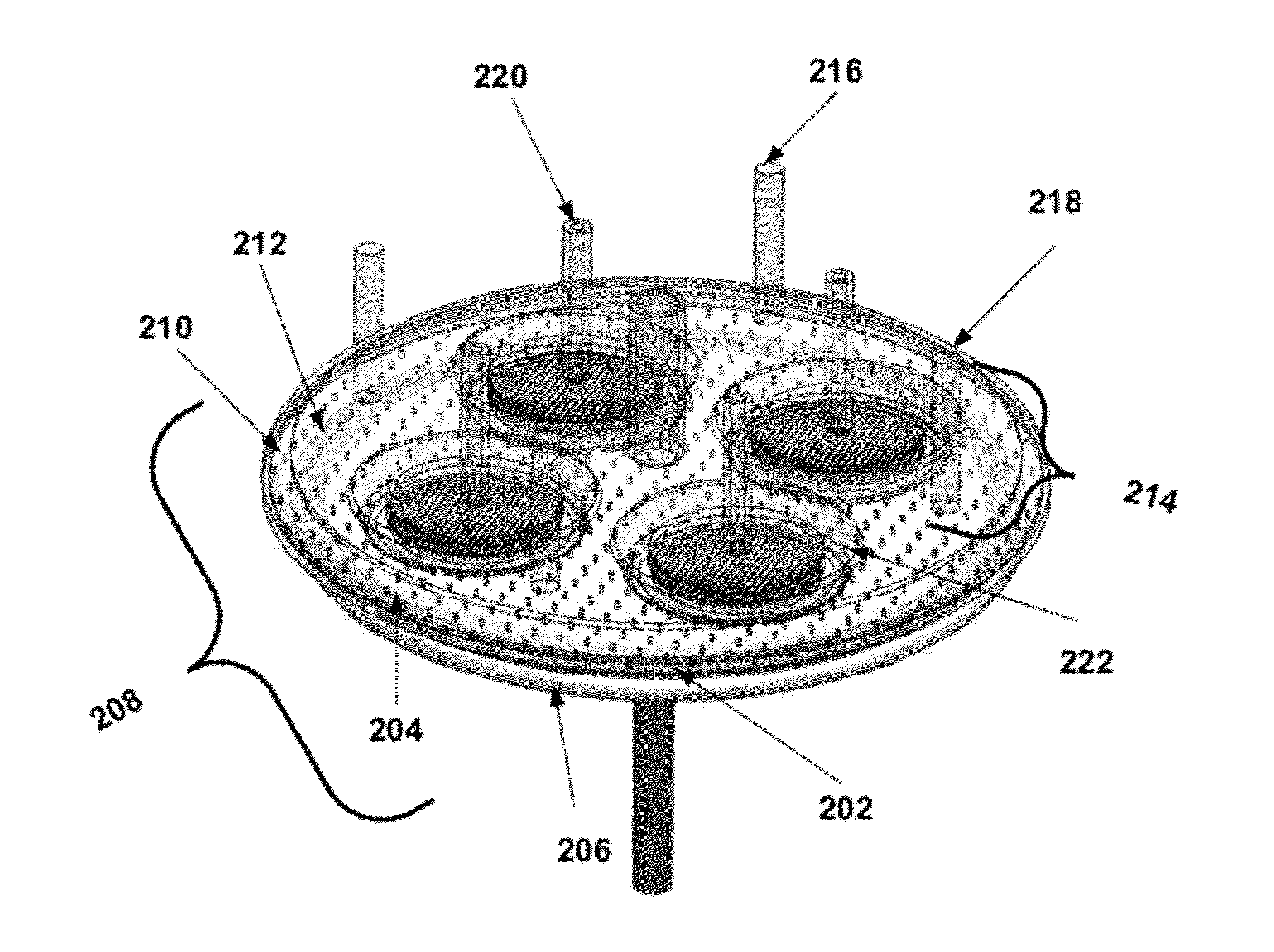
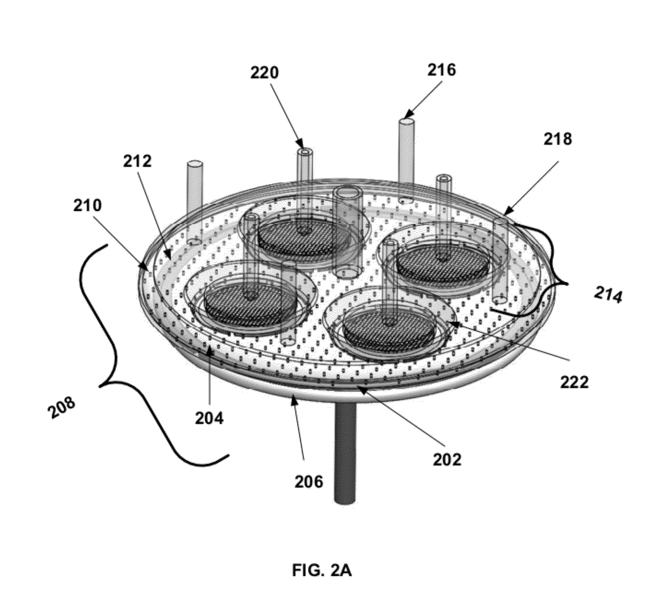
[0009]In some embodiments of the present invention, independent process cells comprise individual showerheads that supply reactants to separate regions of a substrate. The showerheads have the additional advantage in that they have an option to be rotated to include the rotation parameter that may be important in single substrate processing systems. Each process cell is independent of the others and an interstitial purge serves to prevent cross-contamination between adjacent independent process cells. Each process cell may have different characteristics from the others. In some embodiments, the process cells have a circular shape, a triangular shape, a square shape, a rectangular shape, a hexagonal shape, or an octagonal shape.

Problems solved by technology

However, the HPC systems used for development of PVD, ALD, and CVD processes have not implemented a variable for rotation within each site isolated region.
One class of deposition methods that has not been successfully adapted to HPC processing techniques involves the use of metal organic chemical vapor deposition (MOCVD) technologies for the deposition of thin films.
Issues arise in the adaptation of HPC techniques to MOCVD technologies due to the high temperatures and corrosive gases that are typical of MOCVD processes.
These materials are expensive and the development times can be long.

Method used


Image

  • System for multi-region processing
  • System for multi-region processing
  • System for multi-region processing

Examples


Embodiment Construction

[0017]A detailed description of one or more embodiments is provided below along with accompanying figures. The detailed description is provided in connection with such embodiments, but is not limited to any particular example. The scope is limited only by the claims and numerous alternatives, modifications, and equivalents are encompassed. Numerous specific details are set forth in the following description in order to provide a thorough understanding. These details are provided for the purpose of example and the described techniques may be practiced according to the claims without some or all of these specific details. For the purpose of clarity, technical material that is known in the technical fields related to the embodiments has not been described in detail to avoid unnecessarily obscuring the description.

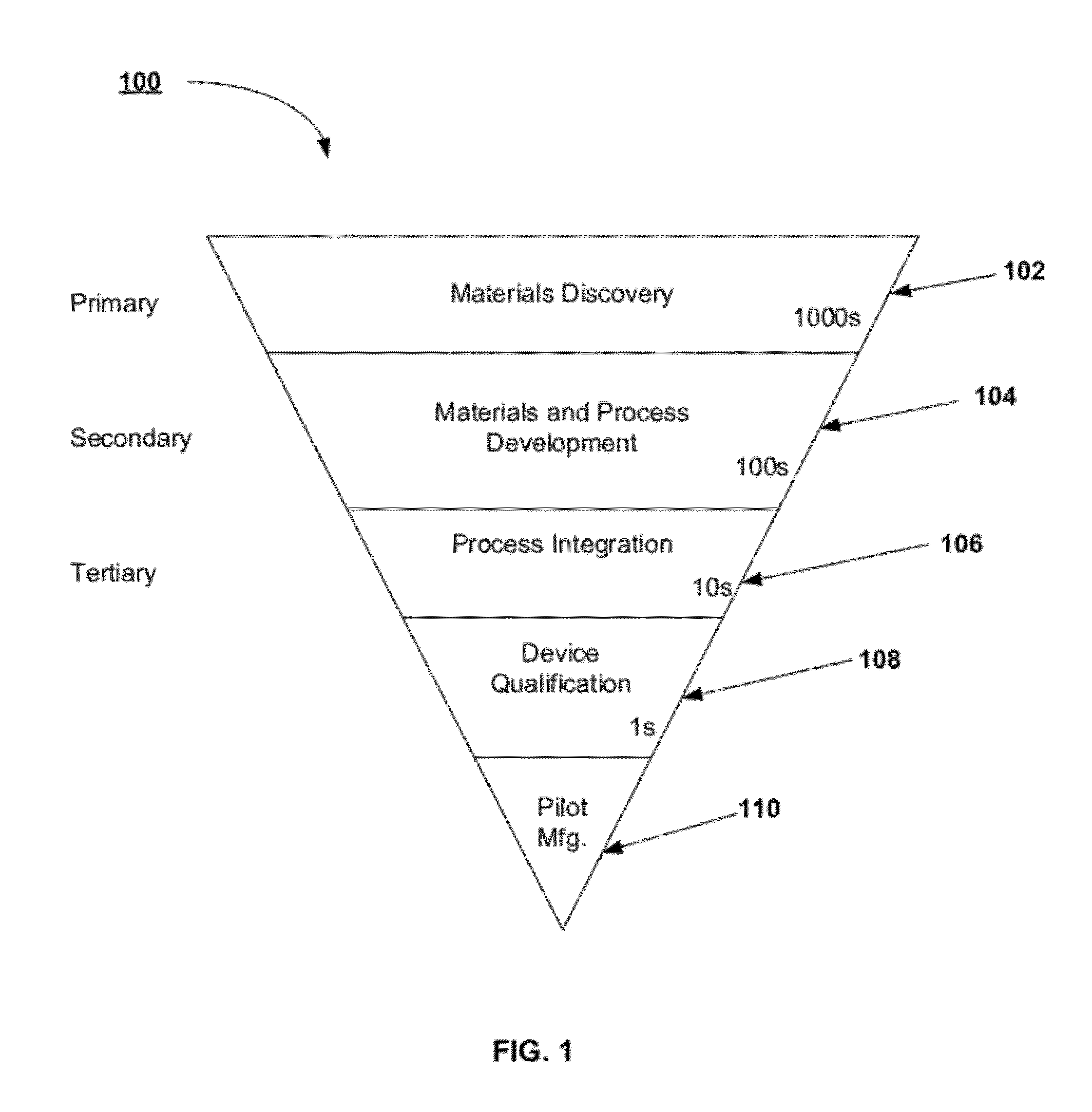
[0018]FIG. 1 illustrates a schematic diagram, 100, for implementing combinatorial processing and evaluation using primary, secondary, and tertiary screening. The schematic dia...


PUM

PropertyMeasurementUnit
Distributionaaaaaaaaaa

Abstract

A gas distribution structure for supplying reactant gases and purge gases to independent process cells to deposit thin films on separate regions of a substrate is described. Each process cell has an associated ring purge and exhaust manifold to prevent reactive gases from forming deposits on the surface of the wafer between the isolated regions. Each process cell has an associated showerhead for conveying the reactive gases to the substrate. The showerheads can be independently rotated to simulate the rotation parameter for the deposition process.

Description

FIELD OF THE INVENTION[0001]The present invention relates generally to systems for high productivity combinatorial materials screening using chemical vapor deposition processes. A specific example will include systems for high productivity combinatorial materials screening using metal organic chemical vapor deposition processes.BACKGROUND OF THE INVENTION[0002]The manufacture of integrated circuits (IC), semiconductor devices, flat panel displays, optoelectronics devices, data storage devices, magneto-electronic devices, magneto-optic devices, packaged devices, and the like entails the integration and sequencing of many unit processing steps. As an example, IC manufacturing typically includes a series of processing steps such as cleaning, surface preparation, deposition, lithography, patterning, etching, planarization, implantation, thermal annealing, and other related unit processing steps. The precise sequencing and integration of the unit processing steps enables the formation of...

Claims


Application Information

Patent Timeline
IPC IPC(8): C23C16/455
CPCC23C16/45565C23C16/52C23C16/46C23C16/4408C23C16/45519C23C16/4401
Inventor SATITPUNWAYCHA, PETERCHILD, KENT
Owner INTERMOLECULAR
Learn More