
Telescopic boom conveyor with operator platform

a technology of operator platform and boom conveyor, which is applied in the direction of conveyors, loading/unloading, lifting devices, etc., can solve the problems of not being able to adjust the operator, using a stepladder may cause safety risks, and not being able to achieve the adjustment of the operator, so as to achieve the effect of reducing one or more problems

Active Publication Date: 2019-07-23
MARSHALLS CONVEYOR SYST
View PDF26 Cites 4 Cited by
  • Summary
  • Abstract
  • Description
  • Claims
  • Application Information

AI Technical Summary

Benefits of technology

The present invention provides a boom conveyor apparatus that is safer, efficient, and easy to use. The mechanism is simple and does not interfere with the operation of the boom, allowing the operator to stand at the correct height for safe and efficient loading and unloading operations. The levelling system maintains the cord in tension, just by the weight of the operator cage, so there is no need for additional structures. Additionally, a compensating mechanism ensures that the operator cage is maintained in a level configuration, regardless of changes in the length of the boom conveyor.

Problems solved by technology

However, this is not an ideal solution as it may not be possible for the operator to adjust the height of the stepladder or platform as the height of the boom changes.
Also, the use of a stepladder may give rise to safety risks.
However, if the boom pivots through a larger angle, the floor of the platform may tilt excessively making the operator platform unstable and dangerous to use.
This problem is most likely to occur if the boom is relatively short, for example less than 10 meters in length when fully extended.
However, the self-levelling mechanism is complex and unsuitable for a boom conveyor that carries a conveyor belt or rollers.
Devising a self-levelling mechanism that is simple and reliable, and that is suitable for use on a pivoting boom conveyor is difficult.

Method used


Image

  • Telescopic boom conveyor with operator platform
  • Telescopic boom conveyor with operator platform
  • Telescopic boom conveyor with operator platform

Examples


Embodiment Construction

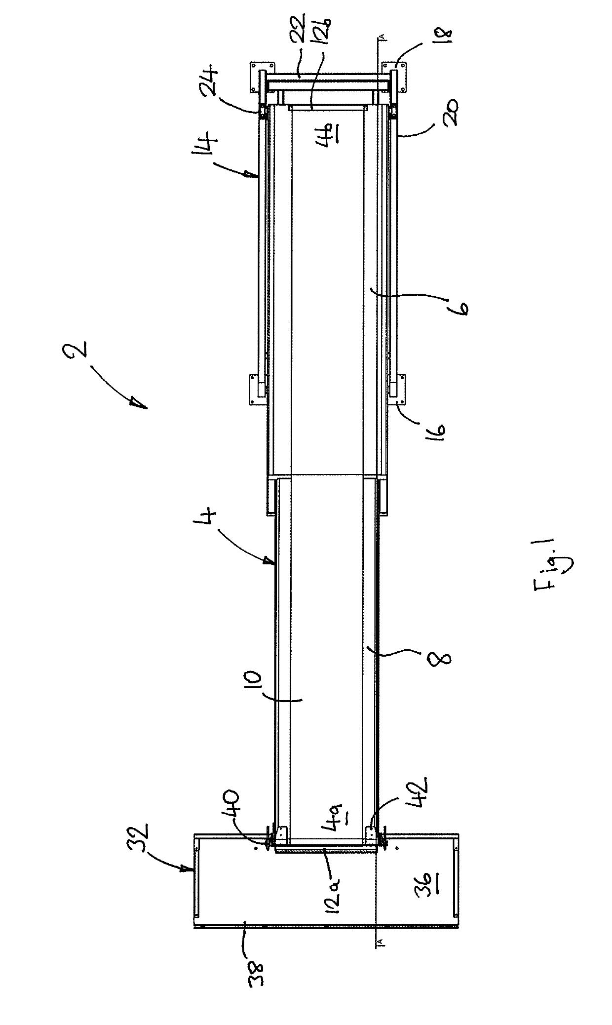
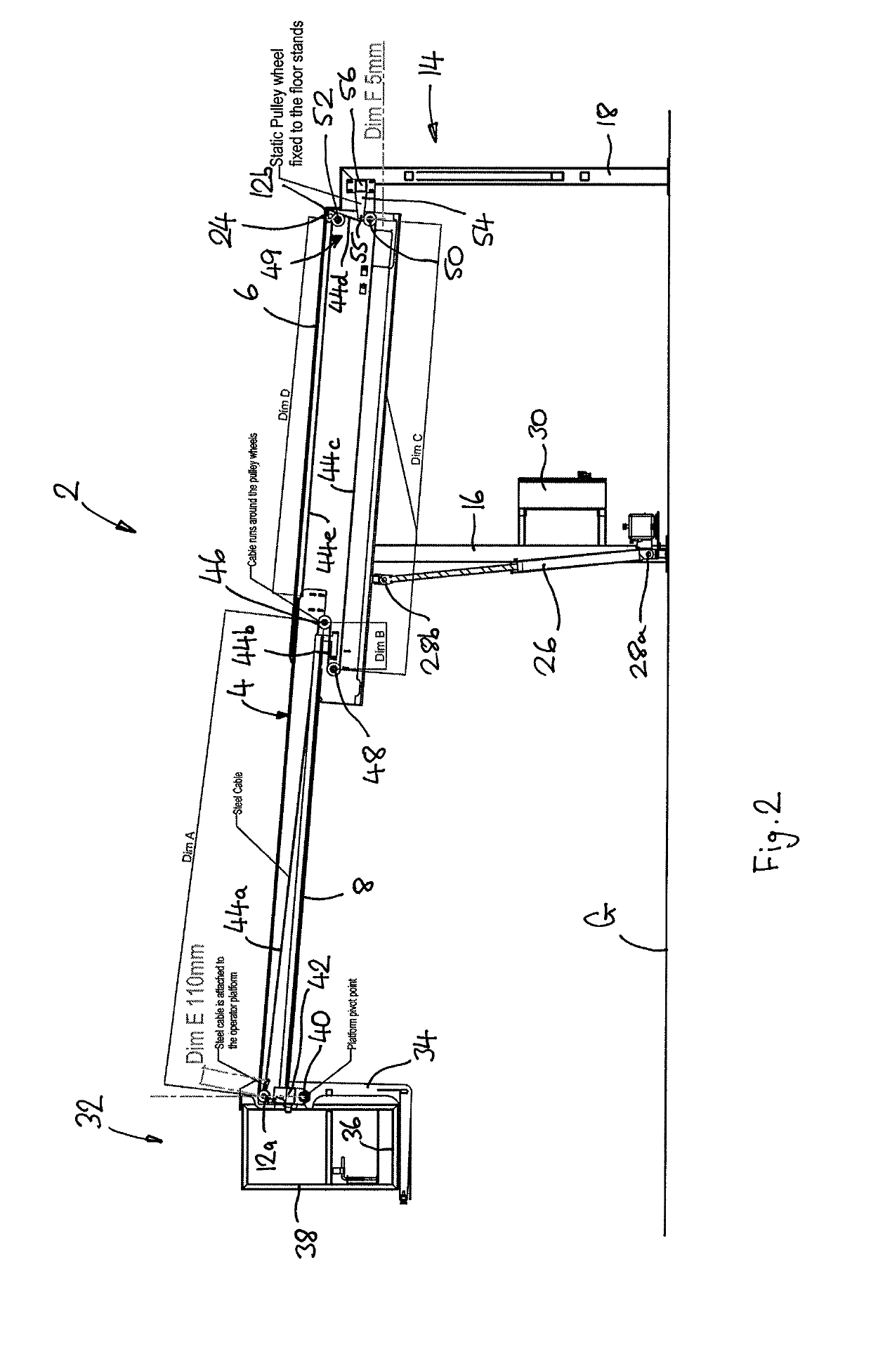
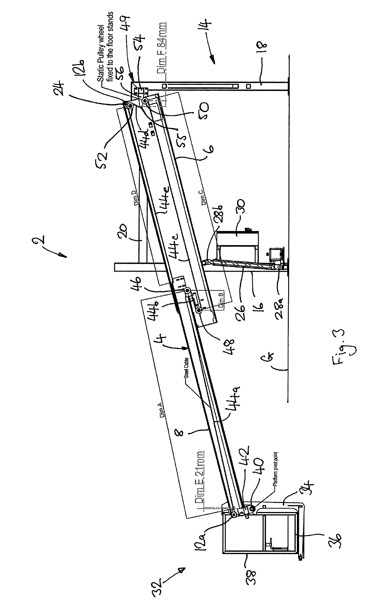
[0025]The loading apparatus 2 shown in FIGS. 1 to 3 includes a boom conveyor 4, which in this embodiment comprises a telescopic boom having a rear boom section 6 and a front boom section 8 that is telescopically extendable relative to the rear section 6 so as to adjust the overall length of the boom conveyor 4. Typically the boom conveyor 4 has a maximum length when fully extended of about 5.5 meters and a minimum length when fully contracted of about 3 meters. However, these dimensions are not intended to be limiting; in certain applications the boom conveyor may have a length when fully extended of 15 meters or more.

[0026]The boom conveyor 4 carries a conveyor, which in this embodiment comprises a conveyor 10 belt that passes around rollers 12a, 12b at the front and rear ends 4a, 4b of the boom. The conveyor belt 10 includes a conveying portion that runs along the upper surface of the boom 4 and a return portion (not shown) that extends through the interior of the boom 4. In the c...


PUM


Abstract

A boom conveyor includes a boom that carries a conveyor, a support structure, a rear pivot joint that connects a rear end of the boom to the support structure, and a pivot drive that controls pivoting movement of the boom. An operator cage is attached by a front pivot joint to a front end of the boom. A levelling system controls rotation of the operator cage about the front pivot joint. The levelling system includes a flexible cord attached to the operator cage and extending towards the rear end of the boom, and a level adjusting device that is attached to the support structure adjacent the rear end of the boom and engages an adjusting portion of the cord. During pivoting movement of the boom, the level adjusting device controls longitudinal movement of the cord relative to the boom so as to apply a levelling adjustment to the operator cage.

Description

FIELD OF INVENTION[0001]The present invention relates to a telescopic boom conveyor for loading and unloading pallets and containers. In particular but not exclusively it relates to a telescopic boom conveyor for use with unit load devices (ULDs), also known as “air cans”, which are used for transporting goods by air. These may be up to 3 meters tall and can contain a variety of goods.BACKGROUND[0002]Upon arrival at a distribution centre, the goods are unloaded via the boom from the ULDs and sorted for delivery to customers / retailers. The ULDs are then reloaded via the boom with other goods for transportation.[0003]The goods are generally loaded and unloaded using a pivoting telescopic boom conveyor that can be extended telescopically and raised / lowered as required. Goods from the ULD are transferred by hand onto the boom conveyor, which then conveys the goods into the distribution centre via either a travelling conveyor belt or a set of rotating rollers.[0004]In order to transfer g...

Claims


Application Information

Patent Timeline
IPC IPC(8): B65G67/02B65G67/08B66F11/04
CPCB65G67/02B66F11/046B65G67/08B65G2207/40B65G15/26
Inventor HENDERSON, MARTIN NEIL
Owner MARSHALLS CONVEYOR SYST
Learn More