
LED headlight

a headlight and led technology, applied in the field of automotive lighting, can solve the problems of serious heat condition and heat dissipation performance of headlights in the market, unsatisfactory refitting of light types of headlights, inconsistent dose, etc., and achieve the effects of simple structure, improved heat dissipation, and high light utilization efficiency

Inactive Publication Date: 2019-07-23
SHENZHEN WEIDELIANG IND CO LTD
View PDF5 Cites 0 Cited by
  • Summary
  • Abstract
  • Description
  • Claims
  • Application Information

AI Technical Summary

Benefits of technology

This configuration ensures consistent and efficient light distribution, enhances heat dissipation, and meets regulatory requirements, increasing the service life and reliability of LED headlights while simplifying the structure and reducing size for easier vehicle integration.

Problems solved by technology

But the structure of the LED headlight has the following problems: first, it is difficult for the LED headlight to achieve the same light effect like a traditional halogen lamp, wherein the traditional halogen lamp lights uniformly; second, the size of a luminous body of the LED headlight is large, which cannot be controlled within a reasonable specification range; third, the heat conduction distance of the LED headlight is long and the sectional area of a heat conduction body is small, which lead that the light type of the headlight refitting is unsatisfactory and dose not consistent with the regulatory requirements, wherein the LED headlight in the market also has serious heat condition and heat dissipation performance.

Method used


Image

  • LED headlight
  • LED headlight
  • LED headlight

Examples


Embodiment Construction

[0025]The following description is disclosed to enable any person skilled in the art to make and use the present utility application. Preferred embodiments are provided in the following description only as examples and modifications will be apparent to those skilled in the art. The general principles defined in the following description would be applied to other embodiments, alternatives, modifications, equivalents, and applications without departing from the spirit and scope of the present utility application.

[0026]The present utility application will be further described in detail with reference to the drawings and embodiments.

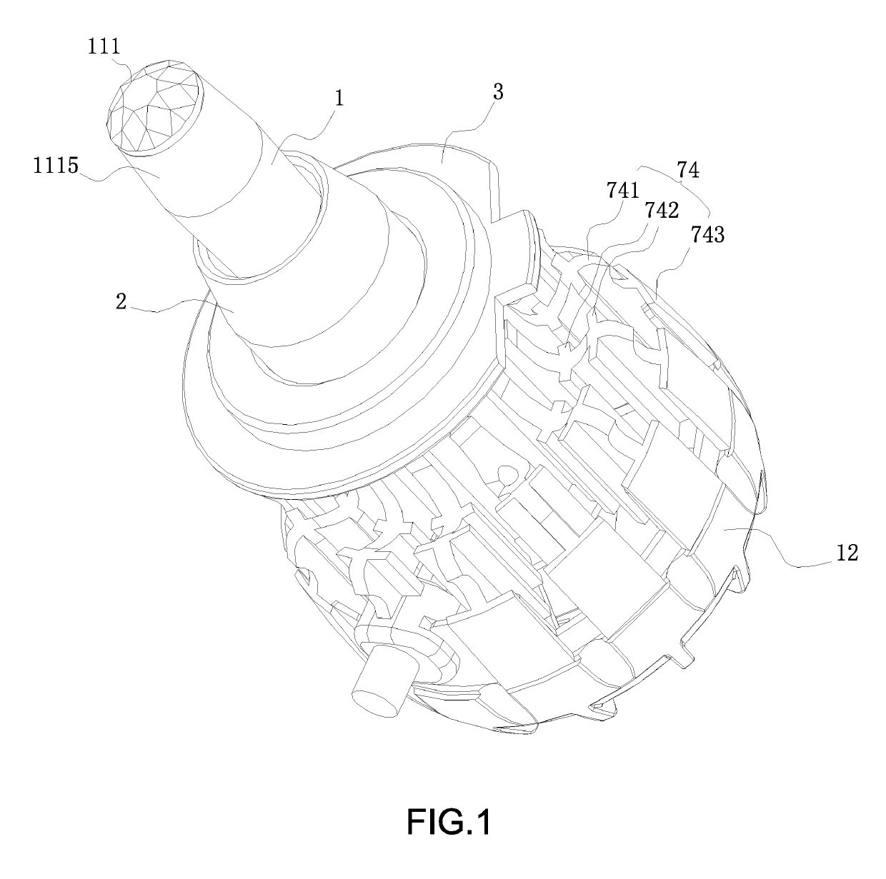
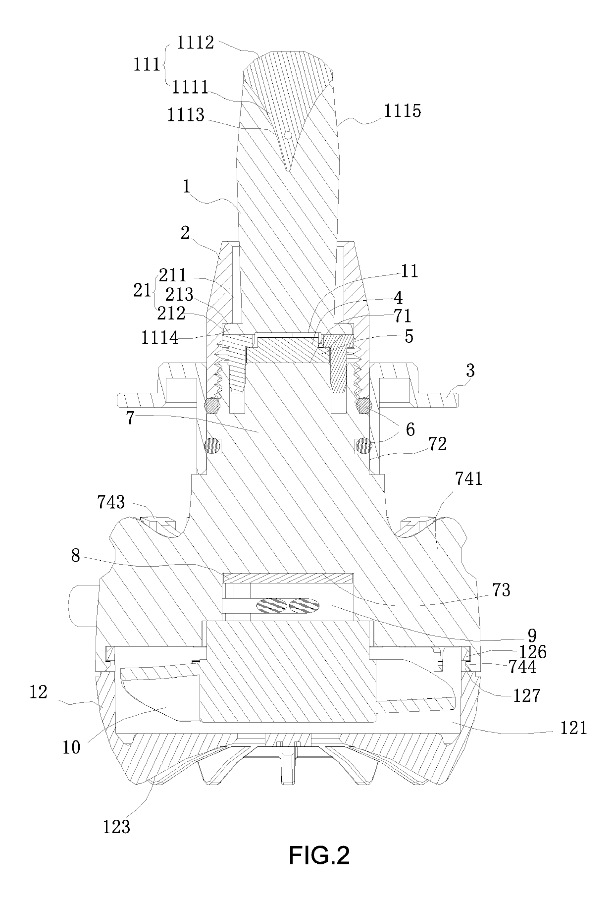
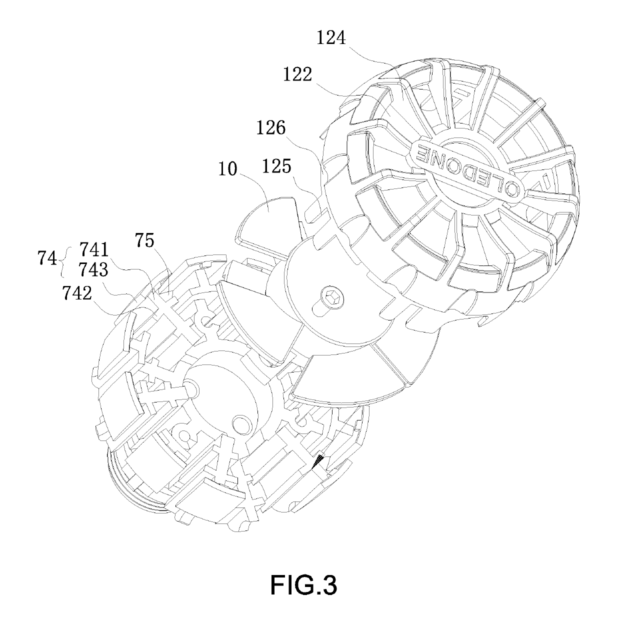
[0027]Referring to FIG. 1 and FIG. 2 of the drawings, an LED headlight according to the present utility application comprises a base plate 5 and a heat sink 7, wherein an LED lamp bead 4 is arranged on the base plate 5, wherein the heat sink 7 is constructed to be a column shape, wherein the heat sink 7 has two end surfaces, wherein one end surface forms a h...


PUM


Abstract

An LED headlight includes a base plate and a heat sink, wherein the LED lamp bead arranged on the base plate, wherein the base plate is fastened on the heat absorption surface, wherein a light guide column is disposed on a luminous side of the LED lamp bead, wherein the light guide column has a light incident surface and a light emitting surface, wherein a reflection head is arranged at one end of the light guide column opposite the light incident surface, wherein the light emitting surface is arranged at an outer periphery wall of the one end of the light guide column corresponding to the reflection head, wherein the light incident surface is arranged towards the luminous side of the LED lamp bead, wherein a rear house is mounted on the assembly surface, wherein a concave first cavity is defined at one end surface of the rear house opposite the assembly surface, wherein a heat dissipation fan is arranged in the first cavity, wherein the air outlet side or the suction side of the heat dissipation fan faces the assembly surface, wherein an air flowing opening communicated with the first cavity is arranged at the rear house. Compared with the prior art, the present utility application achieves transmitting lights by the light guide column, which changes the direction and distribution of the lights, so as to achieve the same luminous position and light uniform distribution in 360°, wherein the service life and the heat dissipation are safer and more reliable.

Description

CROSS REFERENCE OF RELATED APPLICATION[0001]This is a non-provisional application that claims the benefit of priority under 35 U.S.C. § 119 to a China application, application number CN2017214119405, filed Oct. 27, 2017, and the benefit of priority under 35 U.S.C. § 119 to a China application, application number CN2018202782149, filed Feb. 27, 2018.NOTICE OF COPYRIGHT[0002]A portion of the disclosure of this patent document contains material which is subject to copyright protection. The copyright owner has no objection to any reproduction by anyone of the patent disclosure, as it appears in the United States Patent and Trademark Office patent files or records, but otherwise reserves all copyright rights whatsoever.BACKGROUND OF THE PRESENT UTILITY APPLICATIONField of the Present Utility Application[0003]The present utility application relates to automotive lighting, and more particularly to an LED headlight.Description of Related Arts[0004]An LED (light-emitting diode) headlight has...

Claims


Application Information

Patent Timeline
Patent Type & Authority Patents(United States)
IPC IPC(8): F21S41/365F21S41/24F21S41/143F21S45/48F21S41/25F21S45/43
CPCF21S45/48F21S45/43F21S41/24F21S41/143F21S45/47F21S41/192F21S41/29
Inventor SHI, GUANGMING
Owner SHENZHEN WEIDELIANG IND CO LTD
Learn More