
Wide angle, broad-band, polarization independent beam steering and concentration of wave energy utilizing electronically controlled soft matter

a technology of electronic control and wave energy, applied in the direction of instruments, lighting and heating apparatus, optical elements, etc., can solve the problems of prone to wear, limited range of angles over which light can be steered, and potential too costly for some applications, etc., to achieve high angular steering precision and accuracy, large angular steering range, and low loss

Active Publication Date: 2019-08-06
DIDOMENICO LEO D
View PDF1 Cites 1 Cited by
  • Summary
  • Abstract
  • Description
  • Claims
  • Application Information

AI Technical Summary

Benefits of technology

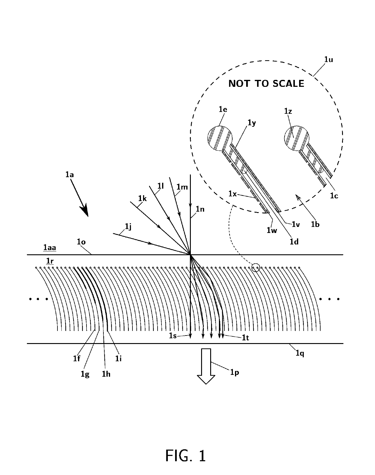
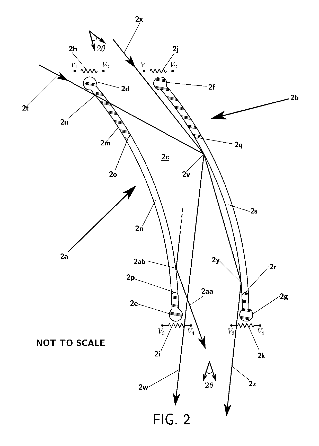
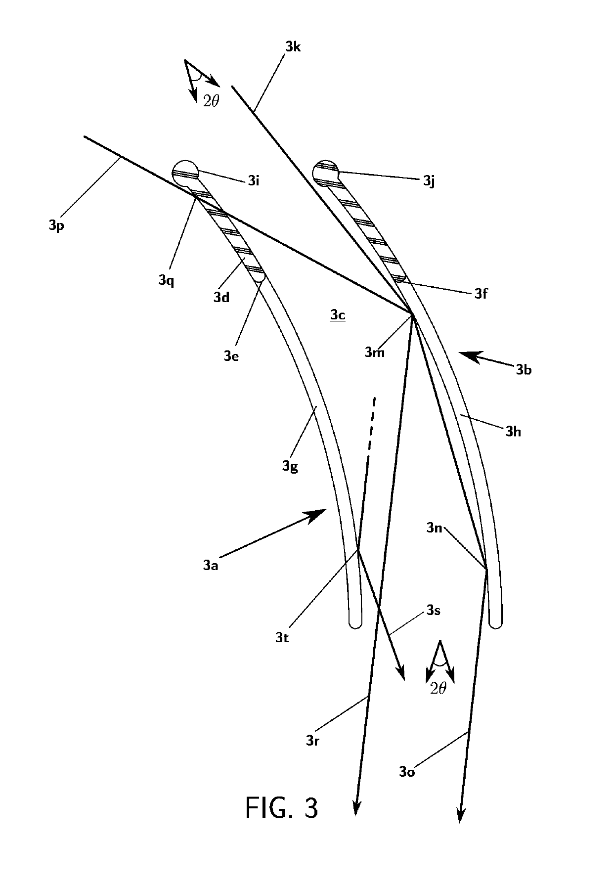
[0017]The technical problem addressed in this patent disclosure is to provide methods and device embodiments that allow electronic control of the propagation direction of freely propagating waves, such waves include, but are not limited to light and sound. The desired devices typically have all or most of the following properties: low loss, broad spectral range (for continuous and / or pulsed waves), large angular steering range, high angular steering precision and accuracy, polarization independence, voltage controllability, low power consumption, capable of processing high-intensity or low-intensity waves, fast responding, thin in profile, configurable to provide wave steering, configurable to provide concentration (or expansion) of waves, an angular field of regard of up to 2π radians in two dimensions and 4π steradians in three dimensions.Solution of the Problem

Problems solved by technology

For example, prior art systems have achieved some capability in beam steering by severely limiting one or more parameters, such as: wavelength, steering angle, polarization, input / output aperture extent and the angular resolution of the light steering.
However, mechanical optical systems often require many components in a complex arrangement, are prone to wear and are potentially too costly for some applications.
This prior art has a limited range of angles over which it can steer light due to the limited range of refractive indices that a liquid crystal can provide.
Yet another limitation of this prior art is that it is a narrowband device that ideally functions on laser light of only one polarization.
Its first shortcoming is that light steering is limited to discrete angles instead of a continuous range of angles unless yet another steering technology is utilized to compensate.
Another shortcoming is that the number of stages within the beam-steering stack limits the overall efficiency, which is strongly affected by: scatter, absorption, and Fresnel loss—which could be significant.
Each of the additional layers requires a lossy transparent conductor further limiting its overall efficiency.
Larger spectral bandwidths would further increase losses.
This means that even through the polarization gratings are inherently very low loss, there is nonetheless at least a loss of 50% of any incident natural light (sunlight or light from a thermal source), which is wasted in a process used to convert the light to the correct polarization before being steered.
While polarization gratings can in principle provide a means to convert natural light to circular polarized light at a normal incident angle, there is at this time no way to also provide for that polarization conversion over a large ±π / 2 radian angular field of regard.
Thus this light steering system is not efficient with broadband polarization-diverse natural light sources such as sunlight.
Some of its shortcomings include that fact that it is limited to reflection only and that the space surrounding each mirror is unused so that significant optical losses are possible.
des. Thus there is a highly restrictive requirement of having input and output waveguides to control the wa
These techniques are limited in area coverage or steering angle range as described in the handbook.

Method used


Image

  • Wide angle, broad-band, polarization independent beam steering and concentration of wave energy utilizing electronically controlled soft matter
  • Wide angle, broad-band, polarization independent beam steering and concentration of wave energy utilizing electronically controlled soft matter
  • Wide angle, broad-band, polarization independent beam steering and concentration of wave energy utilizing electronically controlled soft matter

Examples


first embodiment

[0087]FIG. 6 provides a SPBS device. In particular, a non-fluid soft transparent medium 6a has and array of control channels formed into it. Two examples of these control channels are shown as 6b and 6c. A portion of these control channels is clamped together by electrostatic forces that stretch the medium into a closed configuration and another portion remains unclamped due to a lack of electrostatic forces.

[0088]In particular, control channel 6b has a normally open segment 6d (shown as a dashed curve) that is shown as a closed segment 6e in this figure. The normally open segment is closed by means of voltages that are placed on electrode pairs that run parallel to the control channel 6b, which form an Electrostatic Zipper (EZ). An example of a transparent electrode pair is 6f and 6g. The sign of the voltages is indicated by “+” and “−” signs in FIG. 6 and those electrodes without any sign indication have the same voltage, which is typically zero volts. Control channel 6b has open ...

second embodiment

[0165]To affect the unrolling of a solid cylindrical preform into a slab preform a first distributed particle beam 33h, in the form of a sheet of energetic particles from a first distributed accelerator 33i slices a slab from the rotating cylinder along an internal separation line 33j. In a second embodiment a second distributed accelerator 33k provides a second distributed beam 32m of particles in a sheet, which may be used to form features in the unrolled preform. Again, as in the situation of FIG. 32 the system in FIG. 33 may require that the output slab is annealed to reduce internal stresses after the control channels are formed.

[0166]There also other forms of manufacture. For example the use of 3D printing, such as but not limited to Large Area Projection Micro Stereolithography (LAPμSL), can provide small micron-scale features over meters of area and up to a few tens of millimeters thickness or more.

[0167]The following paragraphs provide some additional disclosures for applic...


PUM

PropertyMeasurementUnit
degree of freedomaaaaaaaaaa
dynamic viscosityaaaaaaaaaa

Abstract

A general method is provided for electronically reconfiguring the internal structure of a solid to allow precision control of the propagation of wave energy. The method allows digital or analog control of wave energy, such as but not limited to visible light, while maintaining low losses, a multi-octave bandwidth, polarization independence, large area and a large dynamic range in power handling. Embodiments of the technique are provided for large-angle beam steering, lenses and other devices to control wave energy.

Description

CROSS REFERENCE TO RELATED APPLICATIONS[0001]This application claims benefit of U.S. provisional patent application Ser. No. 62 / 319,254, filed Apr. 6, 2016, and is a continuation in part of PCT / US2015 / 059797 filed by patent attorney Christopher Peil of the Law Office of Christopher Peil 1701 22nd Avenue, San Francisco Calif. US, 94122 on 2015 Nov. 9 and entitled Wide-Angle Broad-Band, Polarization Independent Beam Steering and Concentration of Wave Energy Utilizing Electronically Controlled Soft Matter, which claims priority from U.S. patent applications: [1] U.S. 62 / 077,371 filed by the inventor, Leo D. DiDomenico, on 2014 Nov. 10 and entitled Efficient Wide-Angle, Broad-Band, Polarization Independent, Electronic Beam Steering and Concentration of Light Utilizing Microfluidics, U.S. 62 / 077,371 is hereby incorporated in its entirety; [2] U.S. 62 / 087,541 filed by the inventor, Leo D. DiDomenico, on 2014 Dec. 4 and entitled Efficient Wide-Angle, Broad-Band, Polarization Independent, E...

Claims


Application Information

Patent Timeline
Patent Type & Authority Patents(United States)
IPC IPC(8): G02B5/10G02B26/08G02B26/00G02F1/29H01L31/054F24S23/70G02B19/00F24S23/79F24S23/00
CPCG02B26/005F24S23/82G02B19/0023G02B19/0042G02B26/004G02B26/0825G02F1/29H01L31/0543H01L31/0547F24S23/70Y02E10/40F24S23/12F24S23/79F24S2023/878G02F2203/24Y02E10/52
Inventor DIDOMENICO, LEO D.
Owner DIDOMENICO LEO D
Learn More