Supercharge Your Innovation With Domain-Expert AI Agents!

FIR filter circuit design method using approximate computing

a filter circuit and computing technology, applied in the field of infinite impulse response (fir) filter circuit design method using approximate computing, can solve the problems of reducing the overall energy efficiency of the system, reducing the number, and the number of adder steps, and achieve the effect of reducing power consumption and acceptable level of accuracy

Active Publication Date: 2019-08-06
UNIST ULSAN NAT INST OF SCI & TECH
View PDF1 Cites 0 Cited by
  • Summary
  • Abstract
  • Description
  • Claims
  • Application Information

AI Technical Summary

Benefits of technology

The present invention is a method for designing a circuit that uses a filter called a finite impulse response (FIR) in image processing applications. The method uses approximate computing to create a higher level of accuracy and reduces power consumption. This allows for better performance and lower energy consumption in image processing devices.

Problems solved by technology

However, because the FIR filter consumes more power due to a complex design thereof, the overall energy efficiency of a system is reduced.
However, these approach only focused on reducing the number of adder steps, providing an accuracy estimation model, or developing an approximate adder, separately.
However, Yao et al. and Malcolm et al. only focused on reducing the number of adder steps.
Also, Choi et al. considered voltage scaling to save power, but the errors incurred along the critical path were observed to usually be more critical than those due to approximations.
Kahng et al. and Gupta et al. applied approximate computing to an FIR filter but did not provide any automated synthesis flow for the approximation.
If the size of the design of the FIR filter becomes larger, it becomes difficult to find optimum configurations for the approximate adders.
As mentioned above, in the conventional FIR filter circuit design method, accuracy is reduced due to the errors incurred by approximations, and large power consumptions is required.

Method used


Image

  • FIR filter circuit design method using approximate computing
  • FIR filter circuit design method using approximate computing
  • FIR filter circuit design method using approximate computing

Examples


Embodiment Construction

[0018]Hereinafter, example embodiments of the present invention will be described in more detail with reference to the attached drawings.

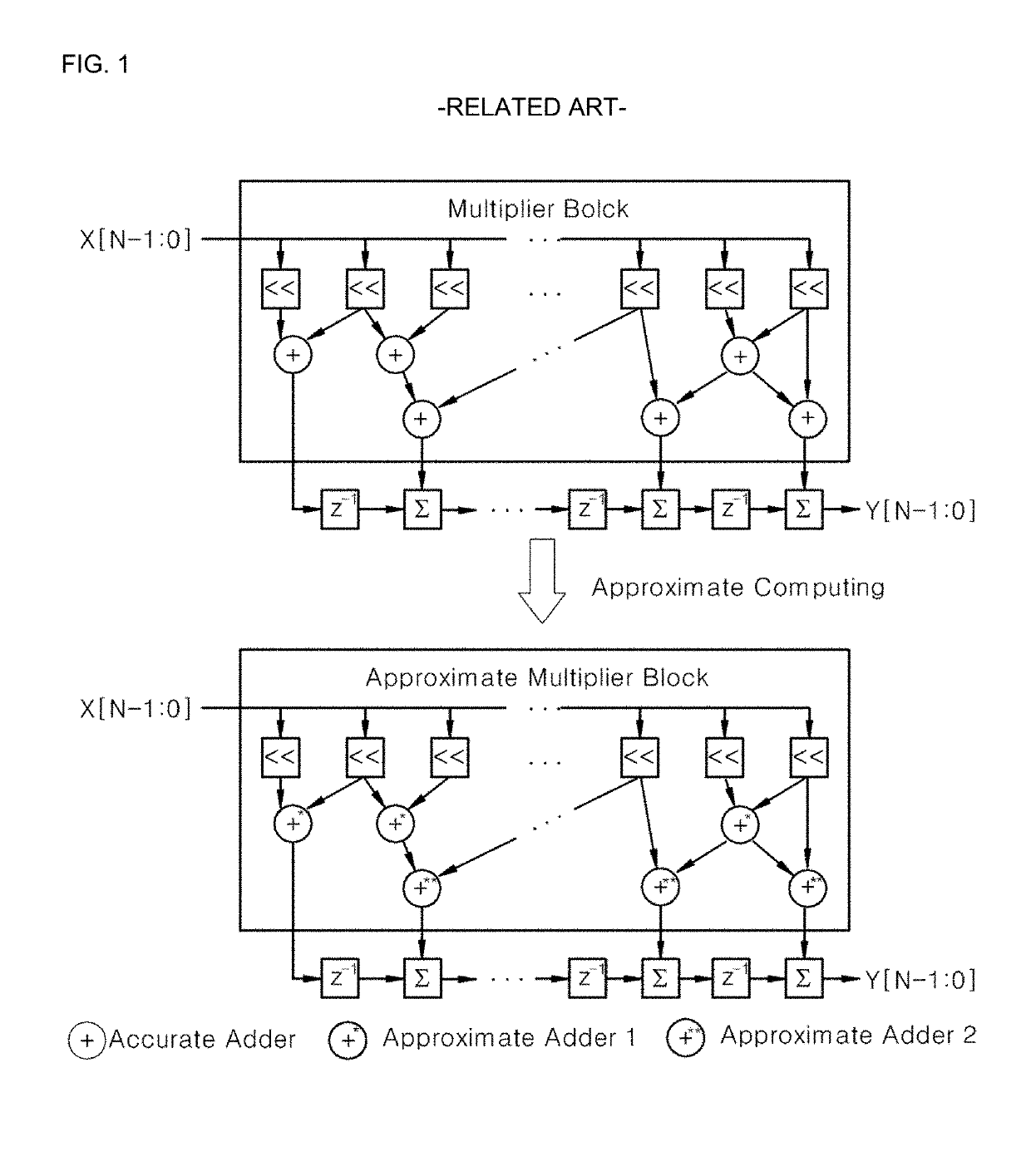
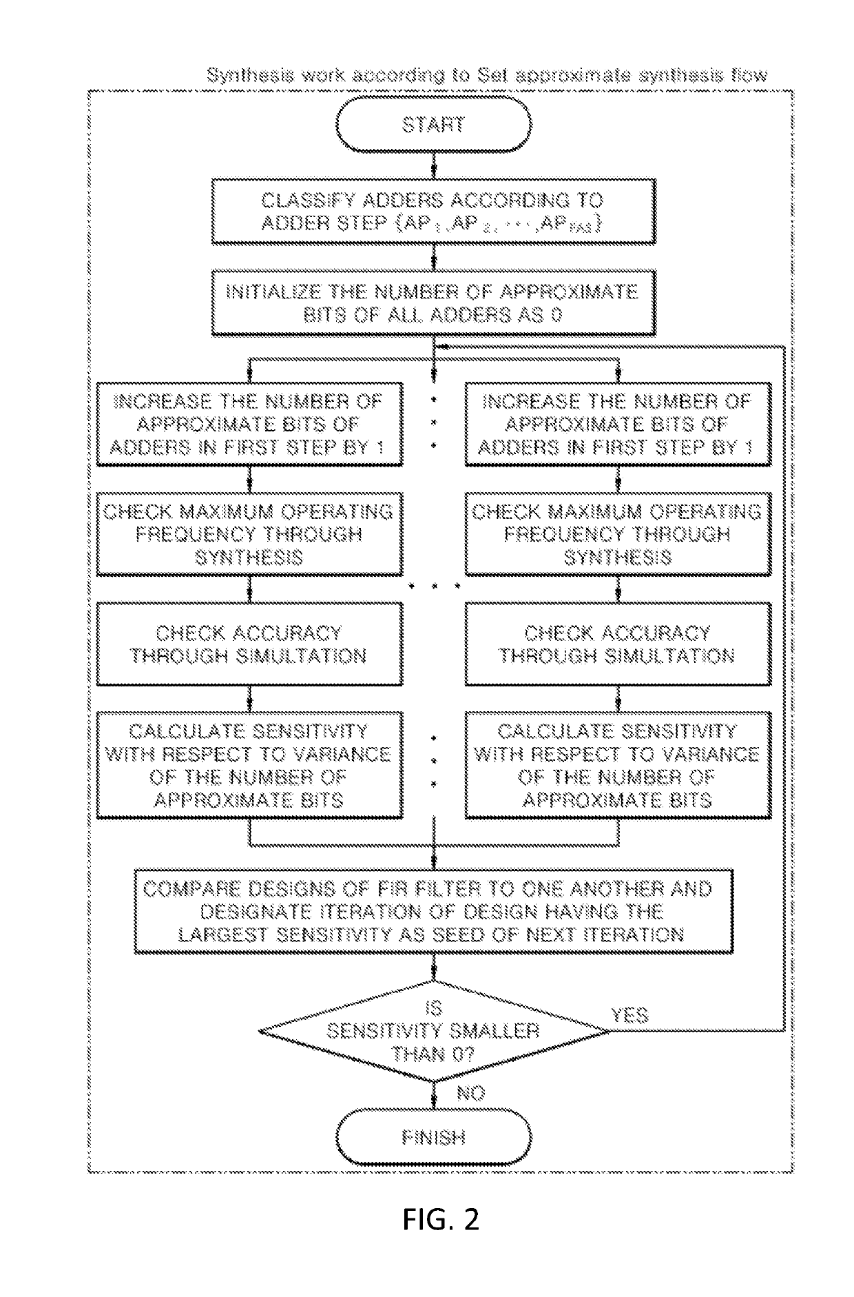
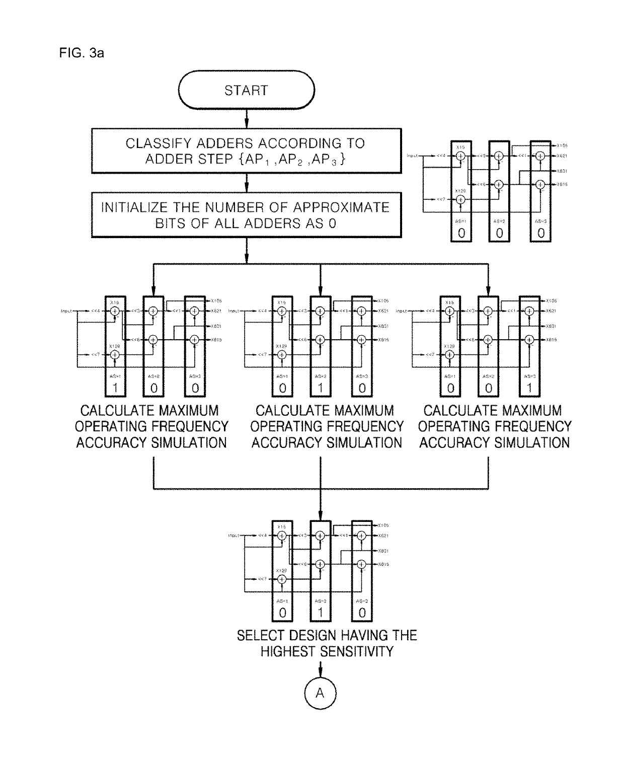
[0019]First, referring to FIGS. 2, 3a and 3b, a finite impulse response (FIR) filter circuit design method using approximate computing according to an embodiment of the present invention includes: replacing adders of an FIR filter with approximate adders and performing a synthesis work according to a set approximate synthesis flow when the replacing of the adders of the FIR filter with the approximate adders is performed.

[0020]Here, in the approximate synthesis flow, a numeric column of each of the approximate adders is divided into an accurate part and an inaccurate part, and a numeric column of the inaccurate part is approximated.

[0021]In the approximate synthesis flow, a boundary position at which the accurate part and the inaccurate part are distinguished from each other, is identically set in the same step. Here, the boundary position is set b...


PUM


Abstract

A finite impulse response (FIR) filter circuit design method using approximate computing, the FIR filter circuit design method including: replacing adders of the FIR filter with approximate adders; and performing a synthesis work according to a set approximate synthesis flow when the replacing of the adders of the FIR filter are replaced with the approximate adders is performed, wherein, in the approximate synthesis flow, a numeric column of each of the approximate adders is divided into an accurate part and an inaccurate part, and a numeric column of the inaccurate part is approximated. In the FIR filter, conventional adders / subtractors are replaced with addition / subtraction having an automated synthesis flow so that energy consumption can be reduced.

Description

CROSS-REFERENCE TO RELATED PATENT APPLICATIONS[0001]This application claims the benefit of Korean Patent Application No. 10-2017-0016179, filed on Feb. 6, 2017, in the Korean Intellectual Property Office, the disclosure of which is incorporated herein in its entirety by reference.BACKGROUND OF THE INVENTION1. Field of the Invention[0002]The present invention relates to a finite impulse response (FIR) filter circuit design method using approximate computing, and more particularly, to an FIR filter circuit design method using approximate computing, whereby an FIR filter applied to an image processing application, etc. is approximated so that power consumption can be reduced.2. Description of the Related Art[0003]As semiconductor technologies continue to develop, electronic devices are becoming smaller and more portable. Consequently, as the battery size of Internet of Things (IoT) devices decreases and power consumption increases, the urgent need for energy efficient systems has gener...

Claims


Application Information

Patent Timeline
Patent Type & Authority Patents(United States)
IPC IPC(8): H03H17/02H03H17/06H03H17/00
CPCH03H17/0238H03H17/0223H03H17/06H03H2017/0245H03H2017/0081G06F17/10H03H17/0621H03H21/0043
Inventor KANG, SEOKHYEONGKANG, YESUNG
Owner UNIST ULSAN NAT INST OF SCI & TECH
Features
  • R&D
  • Intellectual Property
  • Life Sciences
  • Materials
  • Tech Scout
  • Unparalleled Data Quality
  • Higher Quality Content
  • 60% Fewer Hallucinations
Learn More