Internal combustion engine

a technology of internal combustion engine and combustion engine, which is applied in the direction of combustion engine, internal combustion piston engine, machine/engine, etc., can solve the problems of deterioration in combustion stability, and achieve the effects of efficient fuel injection, efficient mixing gas, and efficient spread

Active Publication Date: 2019-08-13
TOYOTA JIDOSHA KK
View PDF15 Cites 3 Cited by
  • Summary
  • Abstract
  • Description
  • Claims
  • Application Information

AI Technical Summary

Benefits of technology

[0007]An object of the present disclosure is to provide a technique that can prevent a main combustion chamber from being in an excessively lean state, regarding an internal combustion engine performing fuel injection in a sub-chamber provided in the main combustion chamber.
[0054]According to the eighth disclosure, the fuel injector is provided in the sub-chamber, and fuel injection is performed in the sub-chamber. The first through-hole larger than another through-hole is formed in the intake side part of the side wall of the sub-chamber. In general, a direction of a tumble flow in the vicinity of the sub-chamber is from the intake side to the exhaust side. Since the comparatively-large first through-hole is formed on the intake side, it is possible to efficiently introduce the tumble flow into the sub-chamber. When the tumble flow enters the sub-chamber through the first through-hole, a mixed gas in the sub-chamber is pushed out into the main combustion chamber through another through-hole. In other words, it is possible by utilizing the tumble flow to efficiently spread the mixed gas in the sub-chamber to the main combustion chamber. Therefore, the main combustion chamber is prevented from being in an excessively lean state. As a result, during the combustion, the flame blowing out from the sub-chamber into the main combustion chamber spreads very well in the main combustion chamber. That is, excellent combustion stability can be achieved.

Problems solved by technology

However, if the main combustion chamber is in an excessively lean state, the flame does not spread well in the main combustion chamber, which causes deterioration in combustion stability.

Method used


Image

  • Internal combustion engine
  • Internal combustion engine
  • Internal combustion engine

Examples


first embodiment

1. First Embodiment

1-1. Basic Configuration

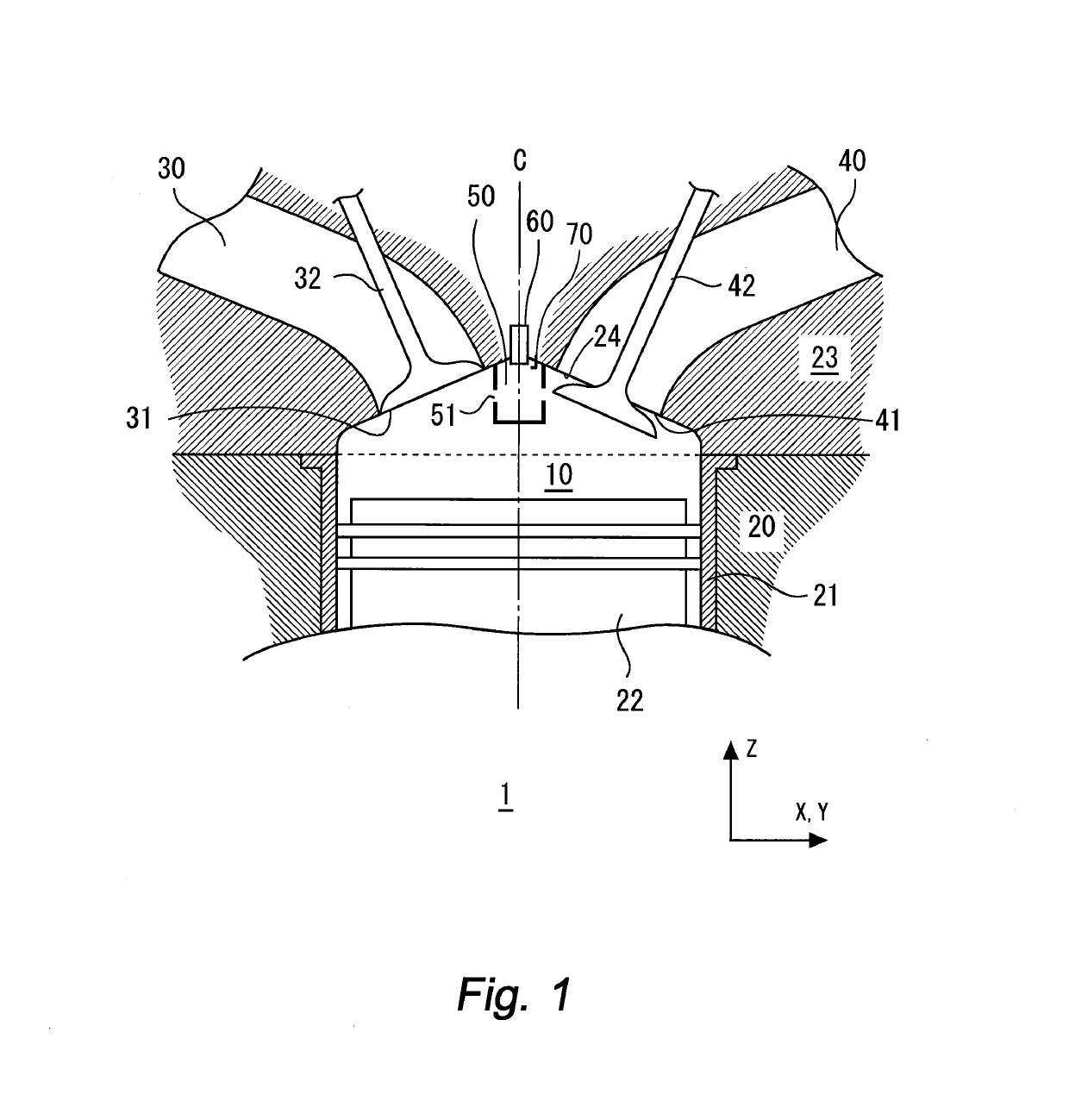
[0070]FIG. 1 is a cross-sectional diagram schematically showing a configuration example of an internal combustion engine 1 according to a first embodiment of the present disclosure. The internal combustion engine 1 is provided with a main combustion chamber 10, an intake port 30, an exhaust port 40, a sub-chamber 50, a fuel injector 60, and a spark plug 70 as major components.

[0071]The main combustion chamber 10 is a space surrounded by a cylinder block 20, a piston 22, and a cylinder head 23. More specifically, the cylinder block 20 includes a cylindrical cylinder liner 21 (cylinder bore) that forms a side wall of the main combustion chamber 10. In the diagram, a central axis of the cylindrical cylinder liner 21 is denoted by a reference numeral “C”. The piston 22 is provided so as to reciprocate in the axis direction of the cylinder liner 21. An upper surface of the piston 22 forms a bottom surface of the main combustion chamber 10. The c...

second embodiment

2. Second Embodiment

[0103]In a second embodiment of the present disclosure, the fuel injected from the fuel injector 60 into the sub-chamber 50 passes through at least a part of the through-holes 51 to directly enter the main combustion chamber 10. The through-hole 51 through which the fuel injected from the fuel injector 60 passes directly is hereinafter referred to as a “direct injection through-hole 51d”.

[0104]FIG. 10 is a perspective view showing a configuration example of the sub-chamber 50 according to the present embodiment. As in the case of the first embodiment, the plurality of through-holes 51 are formed in the side wall 50s of the sub-chamber 50. The plurality of through-holes 51 include the direct injection through-hole 51d (a third through-hole) in addition to the above-described first through-hole 51i. In other words, a part of the plurality of through-holes 51 is formed as the direct injection through-hole 51d. In the example shown in FIG. 10, the direct injection t...

third embodiment

3. Third Embodiment

[0108]FIGS. 13 and 14 are conceptual diagrams for explaining the fuel injection in the sub-chamber 50 according to a third embodiment of the present disclosure. More specifically, FIG. 13 shows the sprayed fuel 90 injected from the fuel injector 60, together with an XY cross-section at the position of the direct injection through-hole 51d. FIG. 14 schematically shows a cross-sectional structure of the sub-chamber 50 along a line F-F in FIG. 13.

[0109]According to the present embodiment, the fuel injection is performed efficiently in consideration of the tumble flow FT flowing from the first side to the second side. More specifically, the fuel injector 60 preferentially injects fuel to a direction of the second side over a direction of the first side. In other words, the fuel injector 60 performs the fuel injection in an asymmetrical manner such that the fuel injection concentrates in the direction of the second side.

[0110]As shown in FIG. 14, the mixed gas formed i...


PUM


Abstract

An internal combustion engine includes: a main combustion chamber; an intake port connected to the main combustion chamber at an intake opening; an exhaust port connected to the main combustion chamber at an exhaust opening; a sub-chamber provided between the intake opening and the exhaust opening, and connected to the main combustion chamber through a plurality of through-holes; a fuel injector injecting fuel into the sub-chamber; and a spark plug performing ignition in the sub-chamber. A tumble flow flows from a first side to a second side as seen from the sub-chamber. The through-holes include: a first through-hole formed in a first side part of a side wall of the sub-chamber; and a second through-hole different from the first through-hole. A diameter of the first through-hole is larger than that of the second through-hole.

Description

BACKGROUNDTechnical Field[0001]The present disclosure relates to an internal combustion engine that performs fuel injection in a sub-chamber provided in a main combustion chamber.Background Art[0002]Patent Literature 1 discloses an internal combustion engine that has a main combustion chamber and a sub-chamber provided in the main combustion chamber. The sub-chamber is connected to the main combustion chamber through a through-hole. A fuel injector and a spark plug are provided in the sub-chamber, and fuel injection and spark ignition are performed in the sub-chamber. Flame generated in the sub-chamber blows into the main combustion chamber through the through-hole.[0003]Patent Literature 2 also discloses an internal combustion engine that has a main combustion chamber and a sub-chamber provided in the main combustion chamber. In the case of the internal combustion engine, a fuel injector is provided in an intake port or the main combustion chamber. In a compression stroke, a portio...

Claims


Application Information

Patent Timeline
Patent Type & Authority Patents(United States)
IPC IPC(8): F02B19/08
CPCF02B19/08Y02T10/125F02B15/00F02B19/00F02B19/18F02B19/108F02B19/12Y02T10/12
Inventor MUTO, TOMOYUKI
Owner TOYOTA JIDOSHA KK
Why Eureka
Try Eureka