
DC circuit breaker combining magnetic induction transfer and resistance current limiting

a technology of magnetic induction transfer and resistance current limitation, applied in the direction of air-break switch, high-tension/heavy-dress switch, electrical apparatus, etc., can solve the problems of high control complexity and cost, unreliable breaking, restricting its promotion and application, etc., to achieve fast transfer speed, reduce volume and manufacturing cost of circuit breakers, and reduce the effect of volume and cos

Active Publication Date: 2019-08-13
XI AN JIAOTONG UNIV
View PDF5 Cites 0 Cited by
  • Summary
  • Abstract
  • Description
  • Claims
  • Application Information

AI Technical Summary

Benefits of technology

[0022]1. In the present invention, the current-limiting branch and the breaking branch are connected in parallel; by controlling turning on and off of the devices at different time, the current rising speed and amplitude of the current is limited, and the short-circuit current is completely cut. In this way, the volume and manufacturing cost of the circuit breaker can be effectively reduced.
[0023]2. Fast current transfer is realized by utilizing magnetic induction transfer modules. The main loop capacitance needs not be pre-charged; isolation between a secondary charging circuit and the main loop enables a fast transfer speed; moreover, the discharging capacitance of the magnetic induction transfer modules adopt a bridge structure, which may two-way limit and break the fault current, thereby greatly reducing the volume and cost.
[0024]3. The main loop capacitor only needs a one-way charging, which may reduce the volume and cost of the capacitor with a high breaking reliability.

Problems solved by technology

A hybrid circuit breaker consisting of a high speed mechanical switch and a power semiconductor device has advantages such as large discharge capacity, fast turn-off speed, and strong current-limiting capability and so on and thus has become a hot issue to study in the field of breaking a large-capacity system.
However, when separating current using the full-control type power semiconductor device, its current transfer loop usually needs a full control type power semiconductor device to cut the current, resulting in a high control complexity and cost, which restricts its promotion and application.
In a traditional transfer current circuit, a capacitor charging circuit is directly connected to a main loop without isolation; during a breaking process, a charging power source and the main loop will suffer interference; besides, it is highly demanding on voltage withstanding of the main loop charging power source, and the breaking is unreliable.
Traditional DC circuit breakers cannot handle the requirements of two-way limitation and separation fault current when tide current in a DC grid is uncertain; or in order to satisfy two-way work scenarios, the size and manufacturing cost of the circuit breakers will always increase significantly.
Because system impedance of a DC power system is very small, when a short-circuit fault occurs, the fault current rises very quickly with a large current amplitude; therefore, it is highly demanding on the current breaking capability of DC circuit breakers, such that the manufacturing technology of the DC circuit breakers is rather difficult with a high manufacturing cost.

Method used


Image

  • DC circuit breaker combining magnetic induction transfer and resistance current limiting
  • DC circuit breaker combining magnetic induction transfer and resistance current limiting
  • DC circuit breaker combining magnetic induction transfer and resistance current limiting

Examples


Embodiment Construction

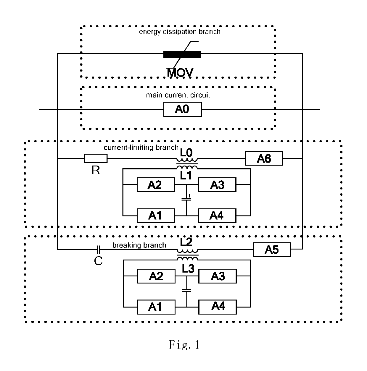
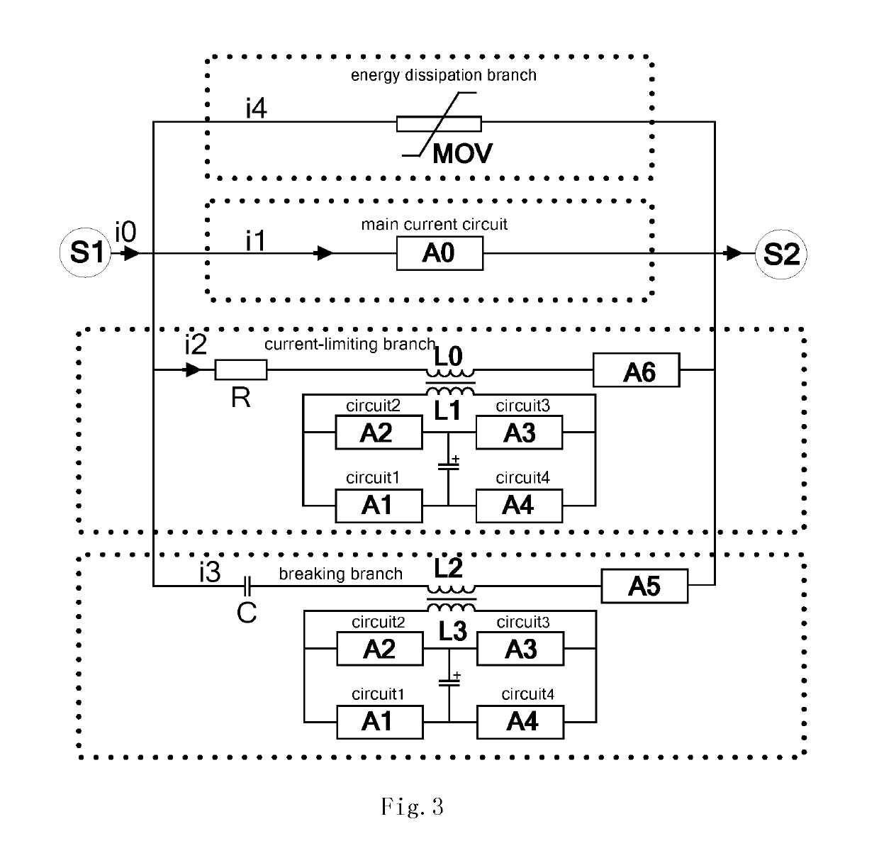
[0041]To enable those skilled in the art to better understand solutions of the present invention. Hereinafter, the technical solutions in the embodiments of the present invention will be described in a clear and comprehensive manner in conjunction with FIGS. 1-13 in the embodiments of the present invention. Apparently, the embodiments as described are only part of embodiments of the present invention, rather than all embodiments. Based on the embodiments in the present invention, all other embodiments obtained by a person of normal skill in the art without exercise of inventive work should fall within the scope of the present invention.

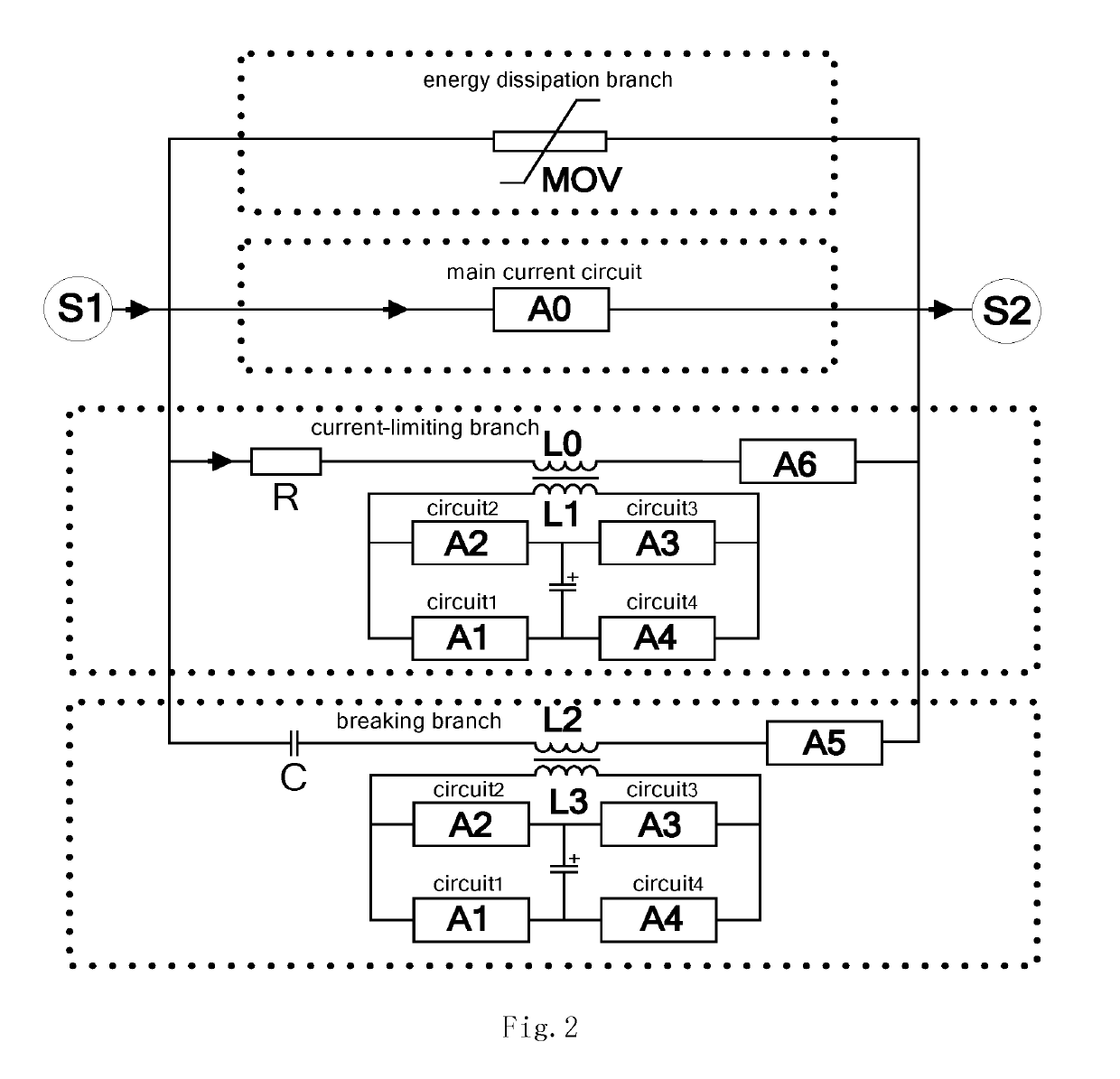
[0042]The present embodiment provides a structural diagram of a circuit breaker body. With FIG. 1 as an example, the circuit breaker comprises a main current circuit, a current-limiting branch, a breaking branch, and an energy dissipation branch.

[0043]In order to better illustrate a separating procedure of a circuit breaker, as shown in FIG. 2, the pr...


PUM


Abstract

The present invention provides a DC circuit breaker combining magnetic induction transfer and resistance current limiting, the circuit breaker comprising: a main current circuit, a current-limiting branch, a breaking branch, and an energy dissipation branch; the current-limiting branch and the breaking circuit each comprises a magnetic induction transfer module; an inductor in the magnetic induction transfer module of the current-limiting branch and a branch inductor in the current-limiting branch are coupled to form a mutual inductor; an inductor in the magnetic induction transfer module of the breaking branch and a second inductor in the transfer current loop are coupled to form a mutual inductor. The present invention can limit the current rising speed and amplitude and completely turned off the short-circuit current, thereby reducing the size and manufacturing cost of the circuit breaker. The main loop capacitance needs not be pre-charged; isolation between a secondary charging circuit and the main loop is realized; the discharging capacitance of the magnetic induction transfer modules adopt a bridge structure, which may two-way limit and break the fault current.

Description

FIELD OF THE INVENTION[0001]The present invention relates to the technical field of electric devices, and more specifically to a DC circuit breaker combining magnetic induction transfer and resistance current limiting.BACKGROUND OF THE INVENTION[0002]A hybrid circuit breaker consisting of a high speed mechanical switch and a power semiconductor device has advantages such as large discharge capacity, fast turn-off speed, and strong current-limiting capability and so on and thus has become a hot issue to study in the field of breaking a large-capacity system. Compared with other hybrid solutions, a hybrid DC circuit breaker that breaks current using a power semiconductor device with a full control function has a faster separating speed and facilitates separation of rational current. However, when separating current using the full-control type power semiconductor device, its current transfer loop usually needs a full control type power semiconductor device to cut the current, resulting...

Claims


Application Information

Patent Timeline
Patent Type & Authority Patents(United States)
IPC IPC(8): H02H3/087H01H9/54H01H33/14H01H33/59
CPCH02H3/087H01H9/542H01H9/548H01H2009/544H01H33/596H01H2009/543H01H33/14
Inventor WU, YIFEIRONG, MINGZHEYANG, FEIWU, YINIU, CHUNPING
Owner XI AN JIAOTONG UNIV
Learn More