
X-ray detection circuit for a dental radiology sensor

a detection circuit and radiology technology, applied in the field of medical imaging, can solve the problems of untimely detection threshold, output signal, and inability to obtain reliable and rapid detection of x-rays with circuits, and achieve the effect of reducing detection thresholds

Active Publication Date: 2019-08-27
TELEDYNE E2V SEMICON SAS
View PDF11 Cites 0 Cited by
  • Summary
  • Abstract
  • Description
  • Claims
  • Application Information

AI Technical Summary

Benefits of technology

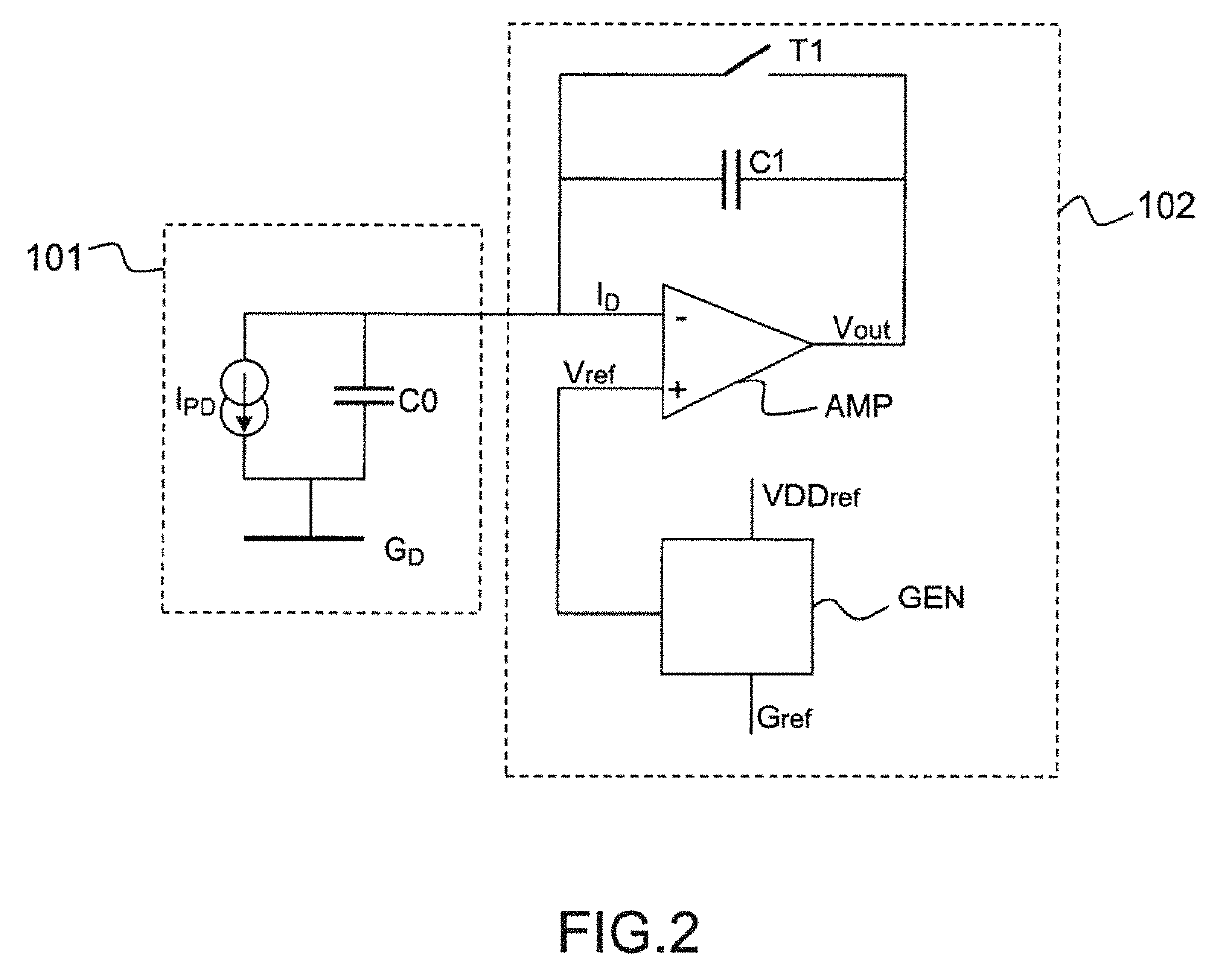
[0009]The invention provides a differential circuit for detecting x-rays that allows variations in external supply voltages to be made irrelevant and, thus, allows the detection threshold to be decreased without increasing the probability of false alarm related to untimely triggering of the detector because of the influence of noise in the amplified signal.

Problems solved by technology

However, the decrease in this threshold leads to another problem.
The absence of stable reference voltage on an input of the amplifier induces variations in the output signal, which may be such that the detection threshold may be exceeded in an untimely way even in the absence of x-rays.
The various solutions described in these documents do not allow a reliable and rapid detection of x-rays to be obtained with circuits using an external supply.

Method used


Image

  • X-ray detection circuit for a dental radiology sensor
  • X-ray detection circuit for a dental radiology sensor
  • X-ray detection circuit for a dental radiology sensor

Examples


Embodiment Construction

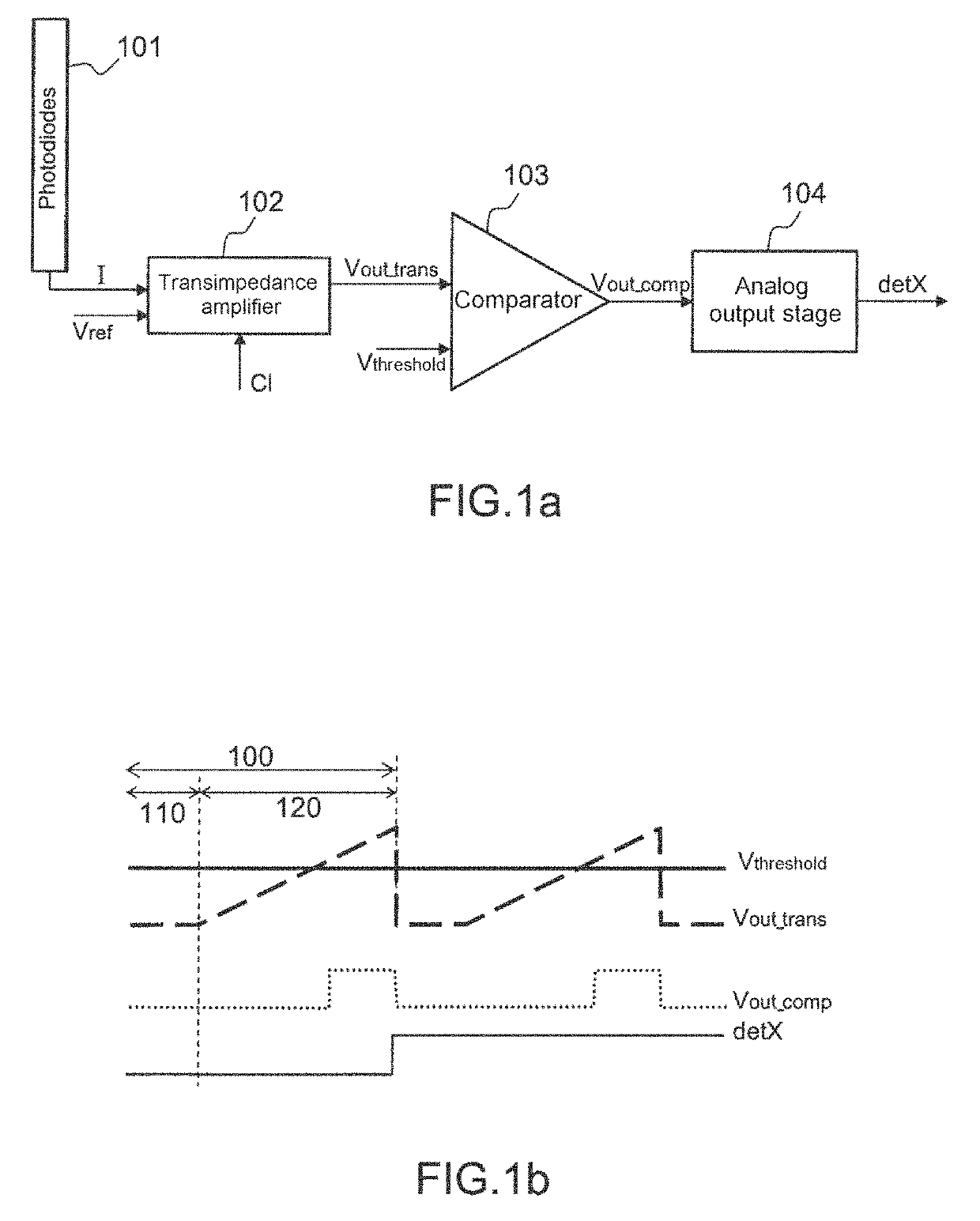
[0032]FIG. 1a shows a functional schematic of a circuit for detecting x-rays for a dental radiological sensor. FIG. 1b illustrates, via a plurality of timing diagrams, the general operation of the circuit.

[0033]A circuit for detecting x-rays mainly comprises a set 101 of photodiodes that are able to receive a flux of x-rays and to convert it into a current I that is delivered to a first input of a transimpedance amplifier 102. Depending on the type of photodiodes 101 used, the current I is directly or indirectly generated by the photodiodes. In particular, the current I is indirectly generated when the radiological sensor uses a material layer called a scintillator that converts, beforehand, the x-rays into visible rays.

[0034]A voltage supply, originating from an external source, is delivered to a second input of the transimpedance amplifier 102, which is clocked by a clock Cl. The amplified signal Vout_trans is then transmitted to a first input of a comparator 103, which receives a...


PUM


Abstract

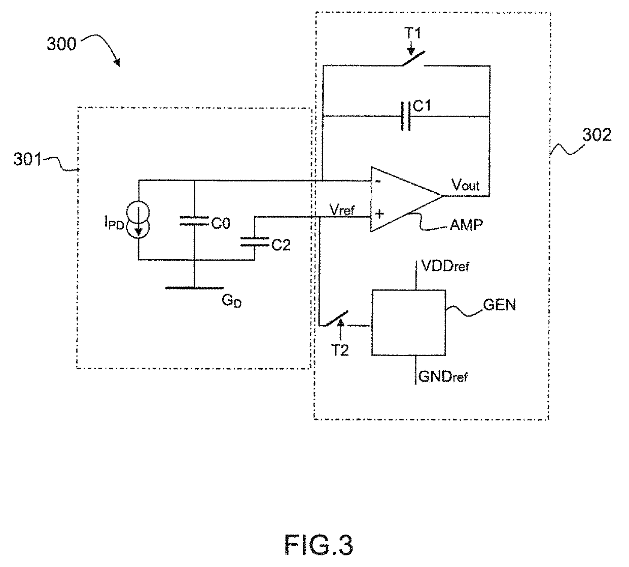
A circuit (300) for detecting the appearance of x-rays with a view to triggering a radiological image capture, comprising a set (301) of photodiodes that is connected to a ground (GD), an amplifying circuit (302) and a capacitor (C2), the amplifying circuit (302) comprising an amplifier (AMP) and a voltage source (GEN) and being connected, via a first input, to the output of the set (301) of photodiodes, the capacitor (C2) being connected between the ground (GD) and a second input of the amplifier (AMP), the detecting circuit (300) being characterized in that the amplifying circuit (302) is configured to carry out in succession the steps of:Charging the capacitor (C2) with a reference voltage (Vref) generated by the voltage source (GEN);Isolating the second input of the amplifier (AMP) from the voltage source (GEN); andIntegrating the current generated by the set (301) of photodiodes.

Description

FIELD[0001]The invention relates to the field of medical imaging, more precisely for dental applications. In this field, dental radiology sensors exist that in particular consist of image-sensor chips in CMOS technology. A radiological sensor allows an image to be acquired by virtue of the emission of x-rays by a source. The sensor receives these x-rays and converts them into visible rays with a layer of specific material, which layer is referred to as a scintillator and is adhesively bonded to the image sensor. The image is obtained via analog read-out of the generated photons in the photodiodes of the pixels, which are located under the scintillator. Depending on the type of photodiode used, the x-rays may be converted directly into an electrical signal without passing via a scintillator.DESCRIPTION OF THE PRIOR ART[0002]In order to synchronize the emission of the x-rays and the start of the acquisition of the image, a radiological sensor must necessarily incorporate a system for ...

Claims


Application Information

Patent Timeline
Patent Type & Authority Patents(United States)
IPC IPC(8): G01T1/24A61B6/00A61B6/14H04N5/32
CPCH04N5/32A61B6/14A61B6/4233G01T1/247
Inventor CHARRAT, CHRISTINEPAPAIX, CAROLINEGESSET, STÉPHANE
Owner TELEDYNE E2V SEMICON SAS
Learn More