Optical system for shaping the wavefront of the electric field of an input light beam

a technology of input light beam and optical system, which is applied in the field of spatial wavefront shaping, can solve the problems that the current 3d cgh optical design cannot be implemented with a conventional scheme for tf, and the axial confinement will quickly deteriorate, so as to achieve accurate compensation and minimize optical aberration

Active Publication Date: 2019-08-27
INST NAT DE LA SANTE & DE LA RECHERCHE MEDICALE (INSERM) +2
View PDF6 Cites 0 Cited by
  • Summary
  • Abstract
  • Description
  • Claims
  • Application Information

AI Technical Summary

Benefits of technology

[0011]Here, the invention presents an optical scheme for non-mechanical remote axial displacement and / or remote axial scanning of spatiotemporal focused patterns and 3D CGH-TF for spatiotemporal focused pattern generation in large volumes, which minimizes optical aberrations and includes accurate compensation protocols to ensure uniform light distribution across the entire accessible volume. The present invention can be also used for non-mechanical remote axial displacement and / or remote axial scanning of fast modulated three-dimensional patterns.

Problems solved by technology

This approach has been largely exploited to generate multi-diffraction-limited traps for optical tweezers and for 3D glutamate uncaging, however only few demonstrations of 3D generation of laterally extended shapes exist and those using high numerical aperture (NA) objectives only proved light generation across a few micrometer axial range.
Moreover, current 3D CGH optical designs cannot be implemented with a conventional scheme for TF because the different excitation planes cannot be simultaneously imaged onto the TF grating and therefore cannot be all temporally focussed.
Therefore, due to the linear proportionality between lateral shape area and axial extent, axial confinement will quickly deteriorate for cases demanding illumination of multiple targets closely distributed or of extended area.

Method used


Image

  • Optical system for shaping the wavefront of the electric field of an input light beam
  • Optical system for shaping the wavefront of the electric field of an input light beam
  • Optical system for shaping the wavefront of the electric field of an input light beam

Examples


Embodiment Construction

[0157]To complete the general description of the optical device of the invention, a detailed description is made.

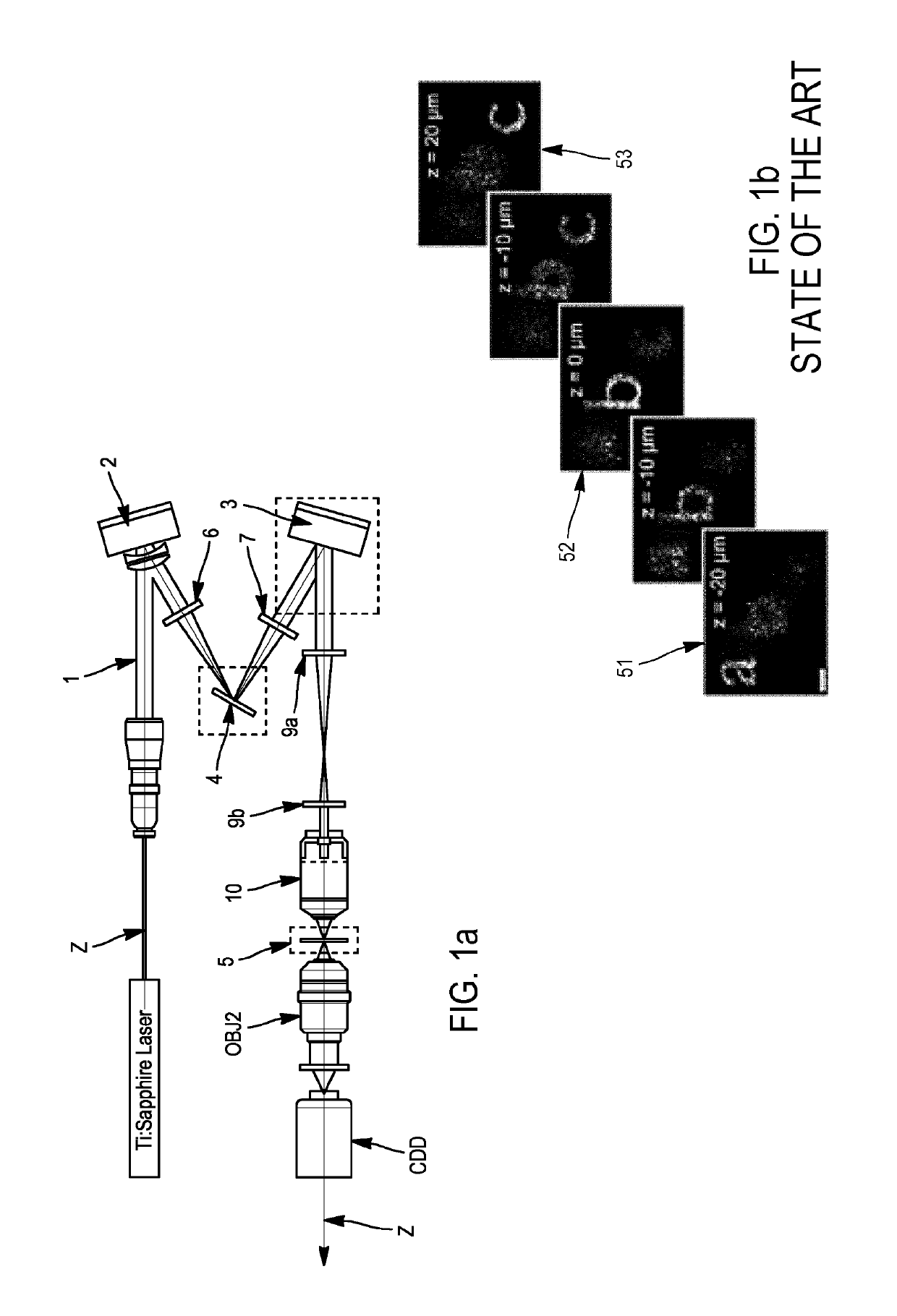
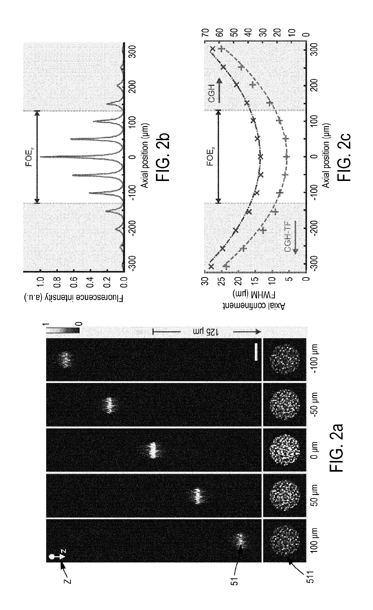
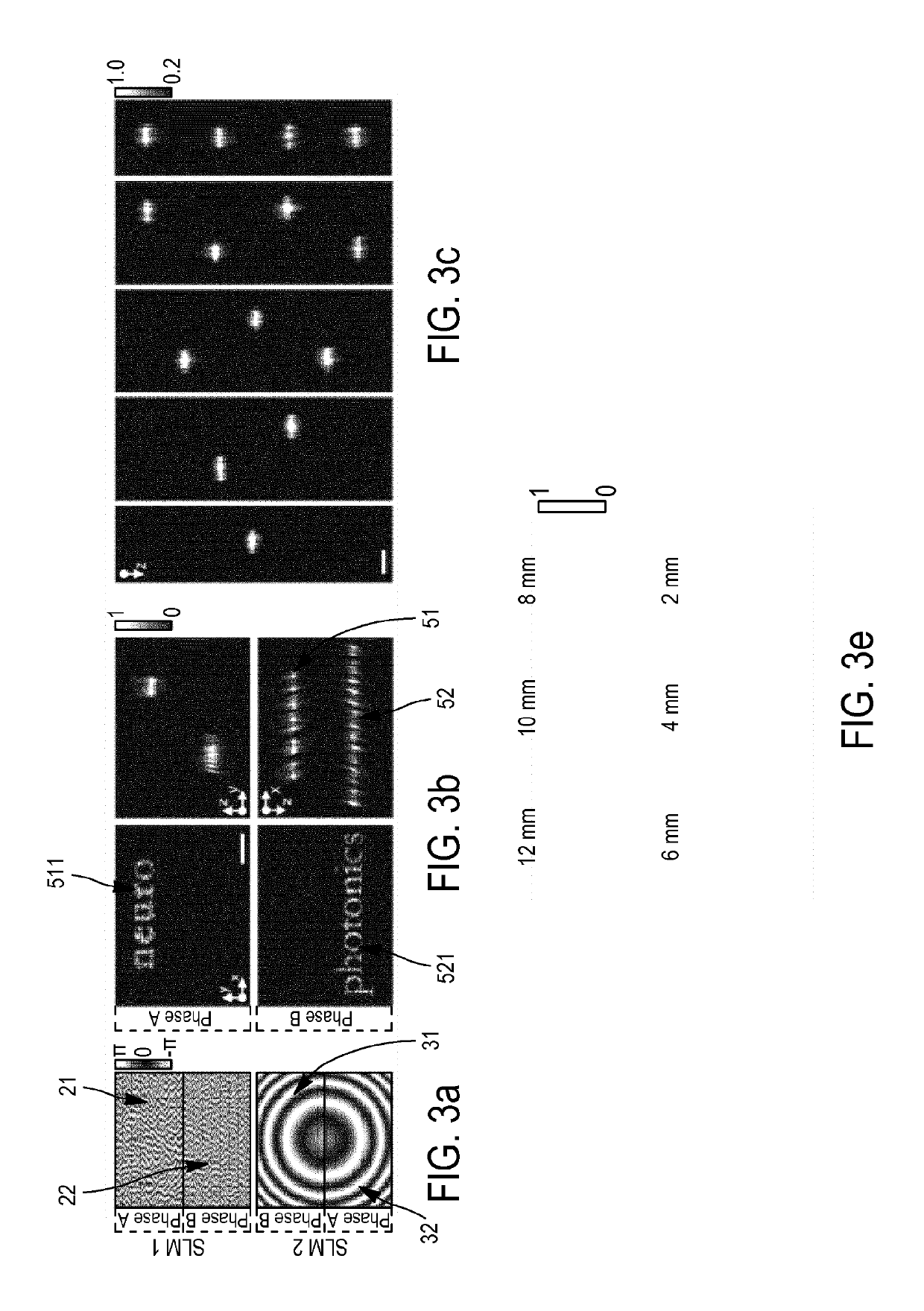
[0158]For the generation of axially confined 3D illumination patterns, we demonstrated a new approach enabling remote axial displacement and / or remote axial scanning of temporally focused holographic patterns and 3D spatiotemporally focused pattern generation. This is achieved by performing a two-steps wavefront shaping of the input light field with two spatial light modulators (SLMs). The first optical element 2 (SLM1) is used to control the target transverse light distribution, the second optical element 3 (SLM2), placed after the grating for TF which is the intermediate optical element 4, is used to control the axial position(s) of the spatiotemporal focus plane(s).

[0159]We demonstrated ability for 3D light generation by simultaneous photoconversion with cellular resolution of neuronal cells expressing the Kaede protein in living zebrafish larvae. Tens of spinal cord n...


PUM


Abstract

An optical system for shaping a wavefront of an electric field of an input light beam to be projected into a target volume including a first optical element, a spatial light modulator used to control light distribution in at least one transverse plane in the target volume. An intermediate optical element located on an optical axis, after the first optical element on a trajectory of the light beam for modulating the phase or the amplitude of the electric field of the input light beam is included. A second optical element for modulating the phase or the amplitude of the electric field of the input light beam is used to control the axial position of the transverse plane in the target volume. The second optical element is situated on the optical axis after the at least one intermediate optical element on the trajectory of the light beam.

Description

FIELD OF THE INVENTION[0001]The invention concerns spatial wavefront shaping.STATE OF ART[0002]Wavefront shaping starts having a strong impact in many diverse research fields of microscopy including structural and functional imaging, neuronal photostimulation and lithography.[0003]Previous systems suggesting temporal modulation of a laser beam with pulse shapers using a SLM between two gratings, and then spatial modulation with another SLM, and which is described for instance in the US Patent US20150010029. In those systems the first SLM of the pulse shaper performs modulation of the spectral phase of the laser beam, thus modulating the temporal profile (pulse duration) of the beam, and the second SLM performs spatial phase modulation of the laser beam wavefront, modulating the intensity distribution of light. A pulse shaper of the state of art uses two gratings, one to disperse the spectral components and one to recombine them to form again the laser pulse, after modulation of its ...

Claims


Application Information

Patent Timeline
Patent Type & Authority Patents(United States)
IPC IPC(8): G03H1/12G02B21/00G02B21/06G02B26/00G02B27/09G02B26/06
Inventor HERNANDEZ-CUBERO, OSCARPAPAGIAKOUMOU, EIRINIVALENTINA, EMILIANI
Owner INST NAT DE LA SANTE & DE LA RECHERCHE MEDICALE (INSERM)
Why Eureka
Try Eureka