Compact high field of view display

a display and high field of view technology, applied in the field of wearable displays, can solve the problems of reducing the optical aberration of the display, affecting the display quality, so as to minimize the optical aberration, and reduce the optical aberration

Active Publication Date: 2021-02-04
SHARP KK
View PDF0 Cites 3 Cited by
  • Summary
  • Abstract
  • Description
  • Claims
  • Application Information

AI Technical Summary

Benefits of technology

[0007]As well as curvature, the one or more lenses include a lens stack having a short focal length. The short focal length enables a device in which the curved screen is at a shorter distance from the user as compared to conventional HMDs. The focal length is low compared to the width of the lens providing a “fast” lens stack, i.e., a lens stack with a low F-number. To reduce optical aberrations, a separate lens is included for each eye of a user. Two or more Fresnel surfaces may be included in the lens stack to further minimize optical aberrations. The lens stack may include lens tinting and circular polarizers to reduce the scattered light introduced by the Fresnel surfaces.
[0008]To increase the FOV of a panoramic HMD while maintaining a simple and compact arrangement, embodiments described herein use a curved lens stack with multiple Fresnel surfaces for each eye of a user. Each curved lens stack can be positioned to direct rays from a curved display screen to a retina of a user. Embodiments described herein provide a modestly sized HMD with lightweight Fresnel lenses and a very wide FOV.
[0009]This approach has several advantages. The curvature of the lenses and display may be configured to wrap around the eye and increase the FOV. A single screen can be used for the entire system, or separate screens can be used for the for each eye of a user. For example, a first screen can provide a first image for the right eye of a user and a second screen can provide a second image for the left eye of the user. The lenses and screens can be designed in a manner that yields a FOV with an angular resolution that corresponds to the resolution of the eye of a user.
[0010]An aspect of the invention, therefore, is a wide field of view display device that employs curved optical components for enhanced performance with a compact arrangement. In exemplary embodiments, a wide field of view display includes a curved display device; a first curved lens having a display side and an exit side, wherein the display side is facing the curved display device; a first plurality of Fresnel facets disposed on the display side of the first curved lens; a second curved lens having a display side and an exit side, wherein the display side is facing the exit side of the first curved lens; and a second plurality of Fresnel facets disposed on the display side of the second curved lens, wherein the first plurality of Fresnel facets is configured to focus light from the curved display device on the second plurality of Fresnel facets, and wherein the second plurality of Fresnel facets is configured to focus light from the first plurality of Fresnel facets on a central image point.

Problems solved by technology

Attempts to increase the immersivity experienced by a user by providing a wider FOV have resulted in larger, heavier, and more expensive devices.
The increase in size and expense of wider FOV HMDs arises partly because the optical components that direct the light paths, such as mirrors in particular, must be fabricated separately and positioned at precise locations in an HMD.
The result is a panoramic HMD that is larger, more complex, and has numerous optical components compared to narrow FOV HMDs.
Additionally, the additional optical components increase the extent of optical aberrations at the edge of the FOV.
As a result, size, weight, and cost deter the adoption and regular usage of panoramic HMDs, leaving users limited to a virtual world in which they can see far less than their eyes can see.
The additional components for mechanical adjustment can undesirably as to the size and weight of the HMD.

Method used


Image

  • Compact high field of view display
  • Compact high field of view display
  • Compact high field of view display

Examples


Embodiment Construction

[0018]Embodiments of the present invention will now be described with reference to the drawings, wherein like reference numerals are used to refer to like elements throughout. It will be understood that the figures are not necessarily to scale.

[0019]Conventional HMDs

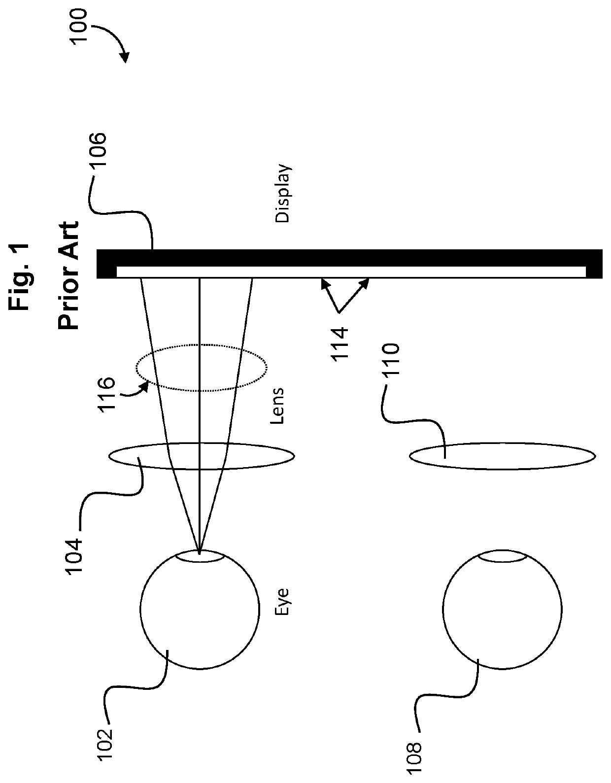
[0020]To better understand the distinctions and advantages of the present invention, comparison is made to conventional HMD configurations. FIG. 1 is a schematic drawing depicting a display arrangement in a conventional HMD 100. The conventional HMD 100 can include a display 106, a first lens 104 associated with a first eye 102 of a user, and a second lens 110 associated with a second eye 108 of the user. The display 106 can show two images 114 side by side. The light 116 from the two images can be collimated by the first lens 104 and the second lens 110 to allow the eyes to focus at a comfortable distance. The conventional HMD 100 limits the field of view (FOV) associated with the eyes of a user to approximately 110°. H...


PUM


Abstract

A wide field of view display device employs curved optical components for enhanced performance with a compact arrangement. A wide field of view display includes a curved display device; a first curved lens having a display side and an exit side, wherein the display side is facing the curved display device; a first plurality of Fresnel facets disposed on the display side of the first curved lens; a second curved lens having a display side and an exit side, wherein the display side is facing the exit side of the first curved lens; and a second plurality of Fresnel facets disposed on the display side of the second curved lens, wherein the first plurality of Fresnel facets is configured to focus light from the curved display device on the second plurality of Fresnel facets, and wherein the second plurality of Fresnel facets is configured to focus light from the first plurality of Fresnel facets on a central image point.

Description

TECHNICAL FIELD[0001]The present disclosure relates generally to display devices, and more specifically to wearable displays that create a panoramic field of view (FOV) in a head mounted display device.BACKGROUND ART[0002]A conventional head mounted display (HMD) can be used to display a virtual world to a user with a FOV around 110°. Attempts to increase the immersivity experienced by a user by providing a wider FOV have resulted in larger, heavier, and more expensive devices. The increase in size and expense of wider FOV HMDs arises partly because the optical components that direct the light paths, such as mirrors in particular, must be fabricated separately and positioned at precise locations in an HMD. The result is a panoramic HMD that is larger, more complex, and has numerous optical components compared to narrow FOV HMDs. Additionally, the additional optical components increase the extent of optical aberrations at the edge of the FOV. As a result, size, weight, and cost deter...

Claims


Application Information

Patent Timeline
Patent Type & Authority Applications(United States)
IPC IPC(8): G02B27/01G02B3/08G02B27/28G02B5/30
CPCG02B27/0172G02B5/3083G02B27/286G02B3/08G02B2027/0123
Inventor SMITH, WILLIAM FREDERICKMONTGOMERY, DAVID JAMESSONG, CHENGZE
Owner SHARP KK
Why Eureka
Try Eureka