
Bidirectional DC-DC converter and control method therefor

a dc-dc converter and bi-directional technology, applied in the direction of electric variable regulation, process and machine control, instruments, etc., can solve the problems of slow reverser recovery characteristics of the body diodes, reduce the soft-switching operation condition of the dc-dc converter, and reduce the rating voltage of the power switch of the dc-ac conversion circuit, reduce the number of power switches, and reduce the loss of the switch

Active Publication Date: 2019-08-27
ABB (SCHWEIZ) AG
View PDF25 Cites 2 Cited by
  • Summary
  • Abstract
  • Description
  • Claims
  • Application Information

AI Technical Summary

Benefits of technology

[0011]Preferably, the switch includes an auxiliary MOSFET; and a body diode of the auxiliary MOSFET of the switch is connected in anti-series with the body diode of the MOSFET of the DC-AC conversion circuit. Thus, the conductive losses of the switch is relatively low accordingly.
[0012]Preferably, the DC-AC conversion circuit is configured of multilevel full bridge topology or multilevel half bridge topology. Thus, the rating voltage for the power switches of DC-AC conversion circuit can be decreased.
[0013]Preferably, the DC-AC conversion circuit includes: a switching leg comprising two of the MOSFETs connected in series; a capacitor leg comprising a pair of capacitors connected in series and being connected with the switching leg in parallel; wherein: both ends of the switching leg are the DC terminals of the DC-AC conversion circuit; the series connection point of the switching leg and the series connection point of the capacitor leg are the AC terminals of the DC-AC conversion circuit. The AC-DC conversion circuit includes: a diode leg comprising two of the power diodes connected in series; and the capacitor leg being connected with the diode leg in parallel; wherein: both ends of the diode leg are the DC terminals of the AC-DC conversion circuit; and the series connection point of the diode leg and the series connection point of the capacitor leg are the AC terminals of the AC-DC conversion circuit. By implementing the DC-AC conversion circuit as a half-bridge configuration, the number of the power switches can be reduced and thus the cost of the DC-DC converter can be lowered.

Problems solved by technology

However, the body diodes of the MOSFETs are used as the output port rectifier for the backward power transmission, the reverse recovery characteristics of body diode of the MOSFET is usually not good enough due to their relatively slow reverse recovery speed and relatively high reverse recovery current or reverse recovery charge, thus bring about relatively high reverse recovery losses.
Besides, slower reverser recovery characteristics of the body diodes may worsen the soft-switching operation condition of the DC-DC converter.

Method used


Image

  • Bidirectional DC-DC converter and control method therefor
  • Bidirectional DC-DC converter and control method therefor
  • Bidirectional DC-DC converter and control method therefor

Examples


first embodiment

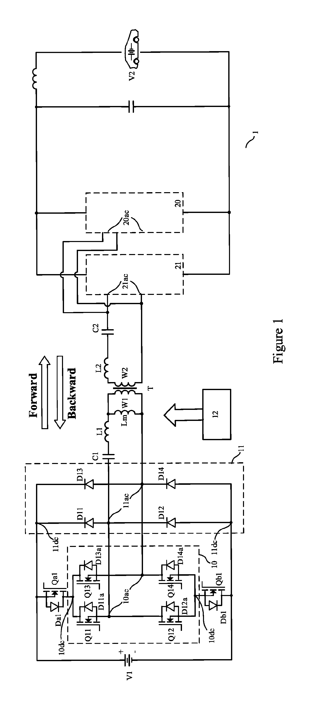
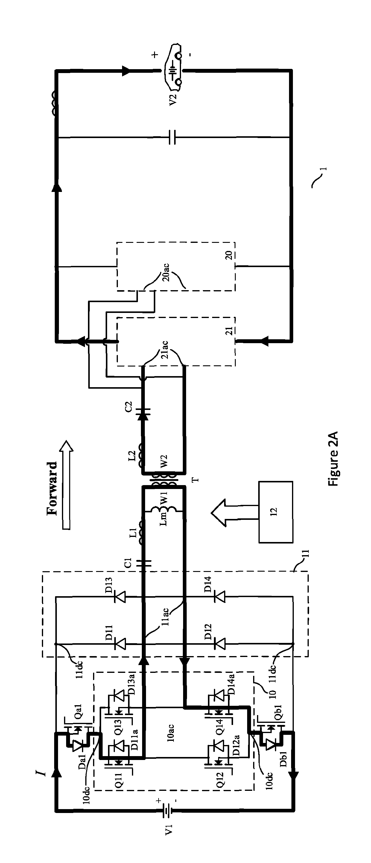
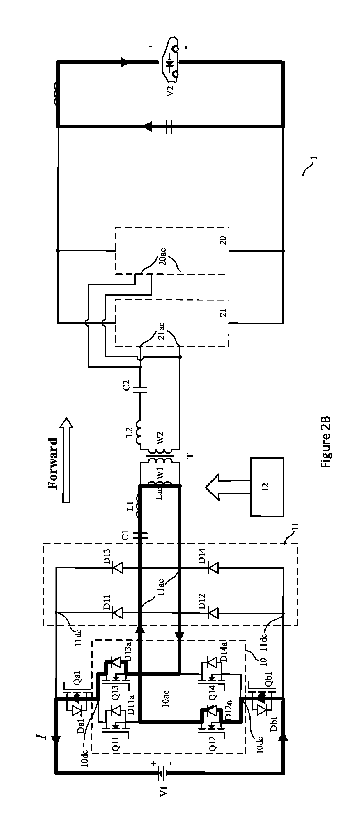
[0026]FIG. 1 is a schematic circuit diagram of a bidirectional DC-DC converter with intermediate conversion into AC power according to present invention. A first DC power supply V1 and a second DC power supply V2 can be electrically connected to the opposite ends of the bidirectional DC-DC converter 1 to transfer electric power between the first DC power supply V1 and the second DC power supply V2. For example, the first DC power supply V1 can be generated from power grid, photovoltaic battery, home power supply, on-board battery of a first EV, and the like, and the second DC power supply V2 can be provided by on-board battery of a second EV; as an alternative, the first DC power supply V1 can be generated from an on-board battery of a first EV and the second DC power supply V2 is powered by power grid, photovoltaic battery, home power supply, on-board battery of a second EV, and the like, as well. The skilled person should understand that electric power can thus flow in a forward d...

third embodiment

[0062]As described above, the bidirectional DC-DC converter according to the embodiment of present invention is specified with examples explaining circuit topology at the side of the first winding W1 and how the bidirectional transmission of DC power based on that. FIG. 5 is a schematic circuit diagram of a bidirectional DC-DC converter with intermediate conversion into AC power according to present invention. As shown in FIG. 5, the circuit topology at the side of the second winding W2 can be implemented according to that of conventional bidirectional DC-DC converter, for example a full-bridge using MOSFETs as described in the Wei Chen et al's paper, where when the forward transmission occurs, the resulting circuit configuration is equivalent to a uncontrolled AC-DC conversion circuit using body diodes of the MOSFETs, and when the backward transmission occurs, the resulting circuit configuration is equivalent to a controlled DC-AC conversion circuit. The DC-AC conversion circuit 20...

fourth embodiment

[0063]As an alternative, the circuit topology at the side of the second winding W2 can use the circuit configuration similar to that at the side of the first winding W1 according to an embodiment of present invention. FIG. 6 is a schematic circuit diagram of a bidirectional DC-DC converter with intermediate conversion into AC power according to present invention. As shown in FIG. 6, the DC-AC conversion circuit 20 can be designed in a circuit configuration similar to the DC-AC conversion circuit 10, including MOSFETs Q21, Q22, Q23, Q24 each having body diode D21a, D22a, D23a, D24a. The AC-DC conversion circuit 21 can be designed in a circuit configuration similar to the AC-DC conversion circuit 11, including power diodes D21, D22, D23, D24. Another pair of switches Qa2, Qb2 are arranged with respect to the DC-AC conversion circuit 20 and the AC-DC conversion circuit 21 in an electrical connection relationship symmetrical to that between the switch Qa1, Qb1 and the DC-AC conversion c...


PUM


Abstract

The invention relates to a bidirectional DC-DC converter with intermediate conversion into AC power, including: a DC-AC conversion circuit using a plurality of MOSFETs; an AC-DC conversion circuit using a plurality of power diodes; a transformer; a pair of switches, one of which being inserted in series between a DC terminal of the DC-AC conversion circuit and the AC-DC conversion circuit and the other of which being inserted in series between another DC terminal of the DC-AC conversion circuit and the AC-DC conversion circuit; and a controller being adapted for turning on the pair of switches such that the plurality of power diodes of the AC-DC conversion circuit are reverse-biased where the AC power is transferred in the forward direction and turning off the pair of switches where the AC power is transferred in the backward direction.

Description

TECHNICAL FIELD[0001]The invention relates to conversion of DC power input into DC power output, and more particularly to bidirectional DC-DC power conversion with immediate conversion into AC power.BACKGROUND ART[0002]Due to demand for decreasing CO2 emission and improving fuel-efficiency of vehicles, there is a rapid development of electric vehicles (EVs). In general, an EV includes at least one on-board battery for driving an electrical motor and for supplying electric power to electronic devices mounted on the vehicle.[0003]Recently, there has been a demand for bidirectional power transmission of EV charger. In addition to charging the on-board battery by electric power supplied from power grid, it would be desirable to transmit electricity from the on-board battery to various electric appliances, such as power grid, home, or on-board battery of another EV. For example, the on-board battery can behave as an emergency power source to supply power from the EV to electric appliance...

Claims


Application Information

Patent Timeline
Patent Type & Authority Patents(United States)
IPC IPC(8): H02M3/335H02M3/337H02M7/5387H02M1/00H02M7/48
CPCH02M3/33584H02M7/5387H02M7/483Y02B70/10H02M3/33573H02M3/01H02M1/0058H02M7/4815H02M3/3376
Inventor YANG, XIAOBOYUEN, KUENFAATFAN, GUOXINGYAO, DAWEICANALES, FRANCISCO
Owner ABB (SCHWEIZ) AG
Learn More