
Cleaning apparatus

a technology of cleaning apparatus and hose, which is applied in the direction of cleaning equipment, suction hoses, roofing, etc., can solve the problems of static electric charge in the electrically generated electricity, triboelectric charging of the hose and its attachments, and electric shock discharge to objects

Active Publication Date: 2019-09-10
SPACE VAC TECH GRP LTD
View PDF39 Cites 6 Cited by
  • Summary
  • Abstract
  • Description
  • Claims
  • Application Information

AI Technical Summary

Benefits of technology

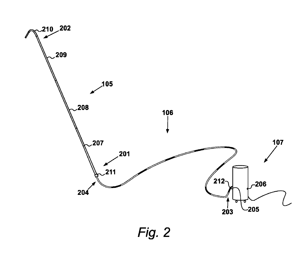
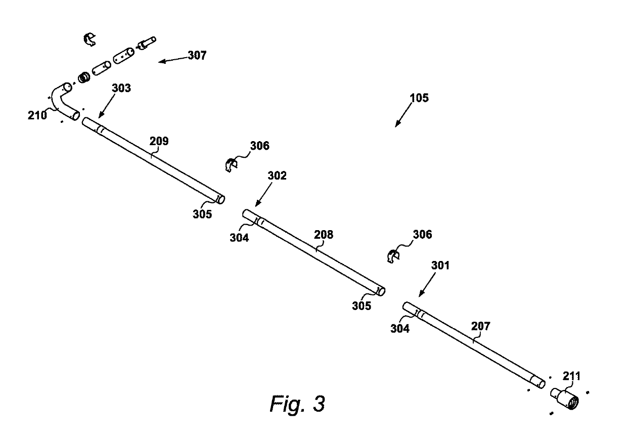
The present invention provides a cleaning apparatus comprising a flexible hose member and a tubular pole member that are mechanically and electrically coupled together to form a fluid conduit. The flexible hose member has first and second open ends, and the pole member has first and second open ends. The hose member and pole member are designed to be attached to a suction unit and a vacuum suction unit, respectively, for mechanically and electrically coupling them together. The apparatus also includes a pole head component for facilitating a suction cleaning operation. The invention provides a high reach suction cleaning apparatus that is easy to assemble and use.

Problems solved by technology

A problem with such conventional vacuum cleaning systems is that of electrostatic discharge from the hose to objects in the surrounding environment.
As is well known, the flow of air and entrained dust particles through the hose and associated attachments of the cleaner causes triboelectric charging of the hose and its attachments.
This results in a build up of static electric charge in the electrically insulative or electrically isolated conductive components of the hose and attachments.
Such electrostatic discharges are undesirable.
They can be damaging to sensitive electronic components, for example, computing equipment, and can result in an unpleasant electric shock to a user of the equipment.
Further, a particular problem exists in commercial and industrial situations, in the presence of flammable products, or where gases and airborne particulates create an explosive atmosphere.
In such environments, a spark caused by an electrostatic discharge may cause ignition of the atmosphere and result in an explosion.
However, such arrangements are less than ideal when considering portable equipment, for example, a portable suction cleaning unit, as the earthing straps must remain connected to electrical earth during operation, and so tend to hinder mobility of the apparatus.
A further problem exists however in that it is common for vacuum cleaning units to be equipped with a rigid extendable pole having interchangeable cleaning heads, which is attached to the end of the flexible hose.

Method used


Image

  • Cleaning apparatus
  • Cleaning apparatus
  • Cleaning apparatus

Examples


Embodiment Construction

FIG. 1

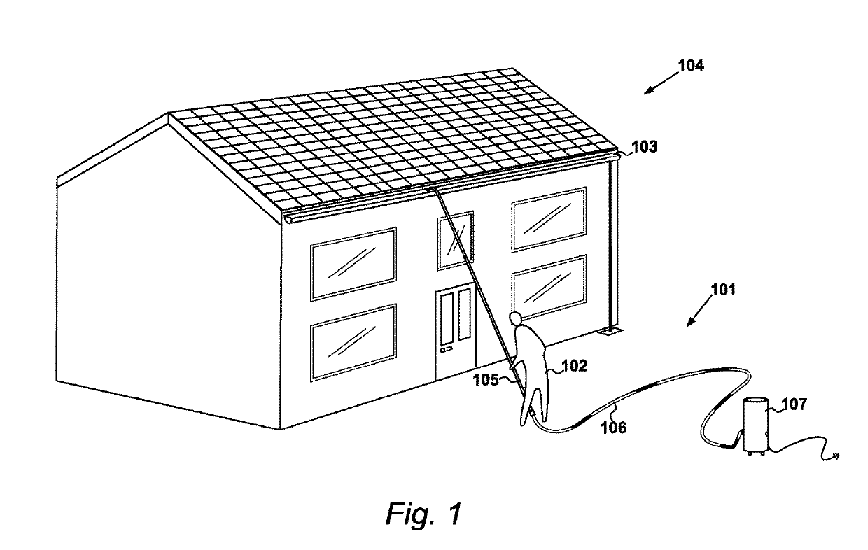
[0057]A cleaning apparatus 101 according to an exemplary embodiment of the present invention is shown in FIG. 1. In the present example, cleaning apparatus 101 is configured as a high-reach anti-static cleaning apparatus, suitable for cleaning areas of buildings that are elevated from ground level.

[0058]As illustrated in the Figure, an operative 102 is using the cleaning apparatus 101 to remove debris, from the gutter 103 of residential building 104. As the skilled person will be aware, guttering's on buildings require frequent cleaning to remove debris, such as leaves and twigs for example, that have accumulated in the gutter over time. Failure to remove such accumulations will eventually result in the gutter becoming blocked, which will prevent rainwater from flowing along the gutter to the downpipe, and will cause the rainwater to instead overflow the sides of the gutter. Conventionally, such a cleaning operation would require an operative to climb a ladder to empty the gut...


PUM


Abstract

A cleaning apparatus for use in explosive atmospheres is disclosed, the cleaning apparatus being configured to conduct to earth any electrostatic charges generated in the components of the apparatus thereby preventing electrostatic discharge. The apparatus comprises a flexible hose member comprised of an electrically conductive material and having first and second open ends, the hose member being suitable for attachment at its first end to a port of an associated suction unit to mechanically and electrically couple said hose thereto; and a substantially rigid tubular pole member comprised of an electrically conductive material and having first and second open ends, said pole member being mechanically and electrically coupled at said first end to the second end of said hose member.

Description

CROSS REFERENCE TO RELATED APPLICATIONS[0001]This application claims priority from United Kingdom patent application No. 16 03 503.2 filed Feb. 29, 2016, the whole contents of which are incorporated herein by reference in their entirety.BACKGROUND OF THE INVENTION[0002]1. Field of the Invention[0003]The present invention relates to a cleaning apparatus, and in particular to a high reach anti-static cleaning apparatus.[0004]2. Description of the Related Art[0005]Vacuum cleaning apparatus are known and used in a variety of situations for lifting debris such as dust, dirt, or other loose contaminants, from a surface. Generally, such vacuum cleaning apparatus include a main suction unit housing an electric motor driven fan and a dust container, and a flexible hose. In use, the electric fan establishes a strong flow of air through the flexible hose, and into the main body, where an air filter element separates dust and debris entrained in the incoming flow of air, causing the separated d...

Claims


Application Information

Patent Timeline
Patent Type & Authority Patents(United States)
IPC IPC(8): A47L5/36A47L9/24E04D13/076
CPCA47L5/365A47L9/244E04D13/0765A47L9/248E04D13/076A47L9/246A47L9/24A47L9/242
Inventor COLLAR, ANDREWPRINCE, WILLIAM STEWART
Owner SPACE VAC TECH GRP LTD
Learn More