Press forming method and method of manufacturing press formed product
a press forming and press technology, applied in the direction of transportation and packaging, vehicle components, etc., can solve the problem of lack of versatility, reduce the residual bending moment of the formed product, reduce the occurrence of camber back in the formed product, and reduce the tensile stress on the outer bent side of the formed produ
- Summary
- Abstract
- Description
- Claims
- Application Information
AI Technical Summary
Benefits of technology
Problems solved by technology
Method used
Image
Examples
first embodiment
(Camber Back)
[0033]First, prior to a description of a press forming method and a method for manufacturing a press formed product according to a first embodiment, a description is made of a camber back occurrence mechanism in general press forming.
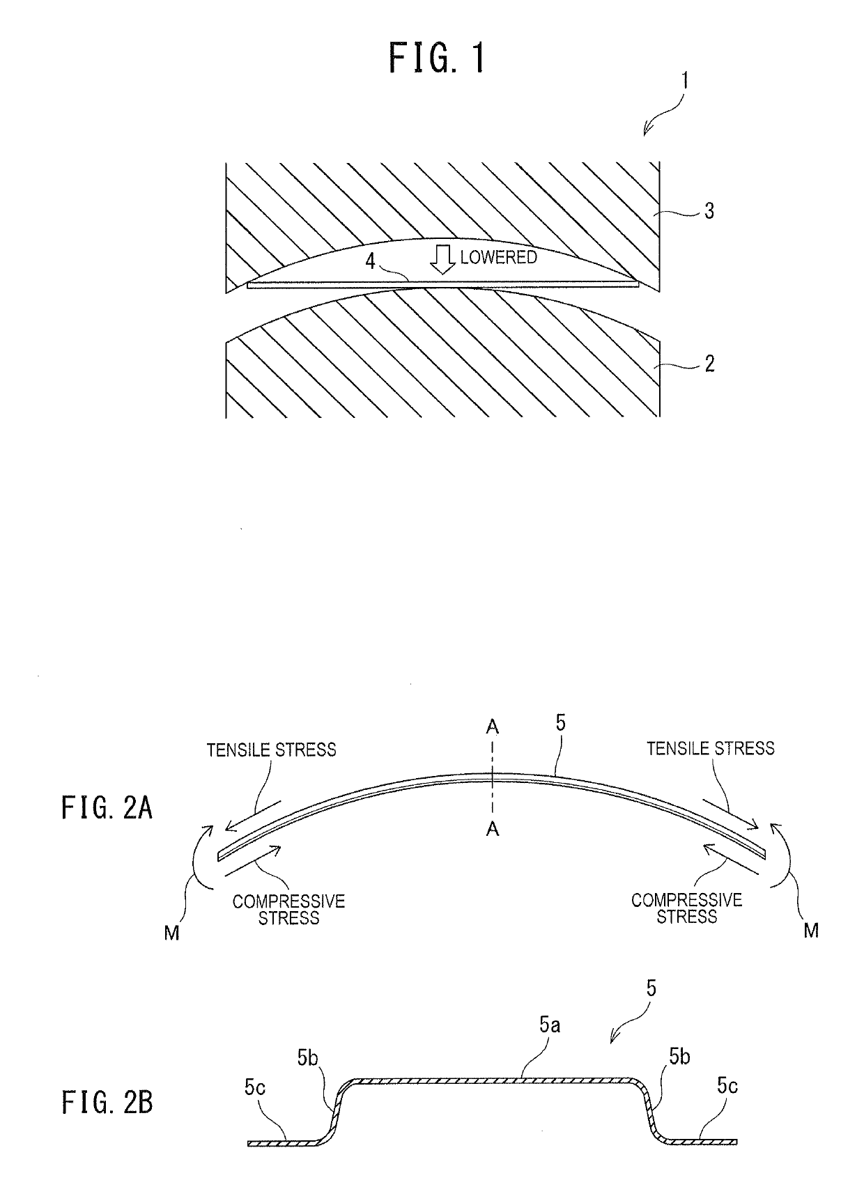
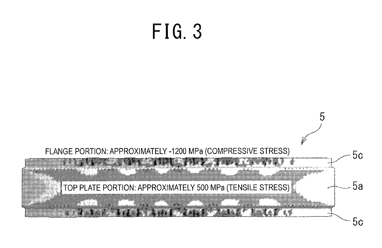
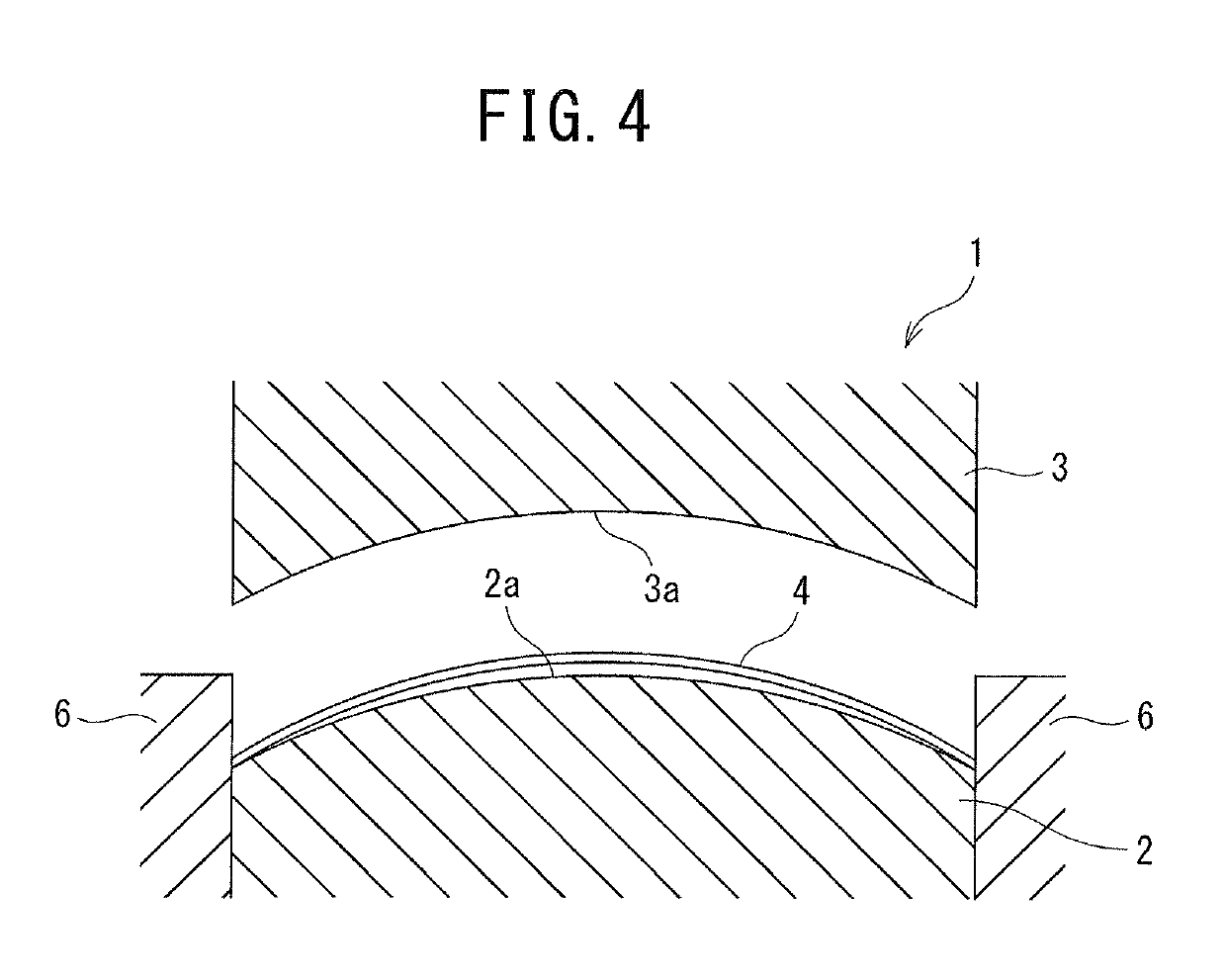
[0034]In usual, as illustrated in FIG. 1 to FIG. 3, when a blank material 4 is manufactured into a press formed product (hereinafter, also referred to as a “hat-shaped member”) 5, which has a hat-shaped cross section and has a bent portion bent to be convex in a direction of a top plate portion 5a, by press forming by using a press forming device 1 (lower die 2, upper die 3), the top plate portion 5a becomes a portion on an outer bent side (convex side), and accordingly, a longitudinal tensile stress is generated in the top plate portion 5a. For example, the blank material 4 is a plate-like raw material cut for the press forming. Moreover, for example, the hat-shaped cross section includes one in which flange portions 5c are further added t...
second embodiment
[0057]Next, a description is made of a second embodiment according to the present invention. Note that the same reference numerals are used for similar constituents and the like to those of the above-described first embodiment, and details thereof are omitted.
[0058]In a press forming method according to the second embodiment, following steps are executed. That is a first forming step of press forming the hat-shaped cross section on the blank material 4, and a second forming step of press forming the bent portion on the blank material 4 on which the hat-shaped cross section is press formed in the first step. Here, in the first forming step, a first press forming device 7 is used. Moreover, in the second forming step, a second press forming device 8 is used.
(Press Forming Device)
[0059]As illustrated in FIG. 9, the first press forming device 7 includes a lower die and an upper die 10 provided above the lower die 9 so as to be capable of ascending / descending. On an upper surface of the ...
modification example
[0073](1) Note that, in the first and second embodiments, the examples of performing the forming as the press forming are illustrated; however, other configurations may be adopted. For example, a configuration of performing draw forming using a wrinkle holder may be adopted.
(2) Moreover, in the first and second embodiments, there are illustrated the examples of forming the hat-shaped member 5, which has such a simple hat-shaped cross section as illustrated in FIGS. 2A and 2B, as the formed product; however, other configurations may be adopted. For example, as illustrated in FIGS. 13A and 13B, there may be adopted a configuration of forming a hat-shaped member 5 having a hat-shaped cross section in which a shape is given to all or apart of the top plate portion 5a.
[0074]Here, FIG. 13A illustrates the hat-shaped member 5 viewed from the side wall portion 5b side, and FIG. 13B illustrates an end surface viewed by cutting the hat-shaped member 5 on a cross section taken along a line B-...
PUM
| Property | Measurement | Unit |
|---|---|---|
| tensile stress | aaaaa | aaaaa |
| size | aaaaa | aaaaa |
| friction coefficient | aaaaa | aaaaa |
Abstract
Description
Claims
Application Information
 - R&D
- Intellectual Property
- Life Sciences
- Materials
- Tech Scout
- Unparalleled Data Quality
- Higher Quality Content
- 60% Fewer Hallucinations
Browse by: Latest US Patents, China's latest patents, Technical Efficacy Thesaurus, Application Domain, Technology Topic, Popular Technical Reports.
© 2025 PatSnap. All rights reserved.Legal|Privacy policy|Modern Slavery Act Transparency Statement|Sitemap|About US| Contact US: help@patsnap.com


