
Mobile ultrasonic rail inspection system and method

a technology of ultrasonic rail and inspection system, which is applied in the field of art of detecting flaws, can solve the problems of inability to achieve good signal coupling between rail and transducer, complication of ultrasonic transmitter and ultrasonic receiver moving with respect to rail, and inability to achieve desirable results, so as to achieve the effect of reducing the inspection pitch and substantially increasing the maximum operational speed of the inspection vehicl

Inactive Publication Date: 2019-09-24
SONIMEX BV
View PDF10 Cites 0 Cited by
  • Summary
  • Abstract
  • Description
  • Claims
  • Application Information

AI Technical Summary

Benefits of technology

[0007]An object of the present invention is to improve on the existing technology so that the maximum operational speed for the inspection vehicle can be substantially increased or the inspection pitch can be reduced, or both. The principle proposed by the present invention is applicable in each type of wheel-type inspection system, and will result in an improvement in each system as compared to the capabilities of such system without the invention, ceteris paribus, but the extent of the improvement may depend on the actual system.

Problems solved by technology

However, although the measurements could be performed stationary from a technical point of view, this is not desirable from a practical point of view, because the railroad should remain open for railroad traffic.
Such mobile systems, however, introduce the complication that the ultrasonic transmitter and the ultrasonic receiver are moving with respect to the rail under inspection.
One aspect of this complication is that it is more complicated to achieve a good signal coupling between rail and transducer.
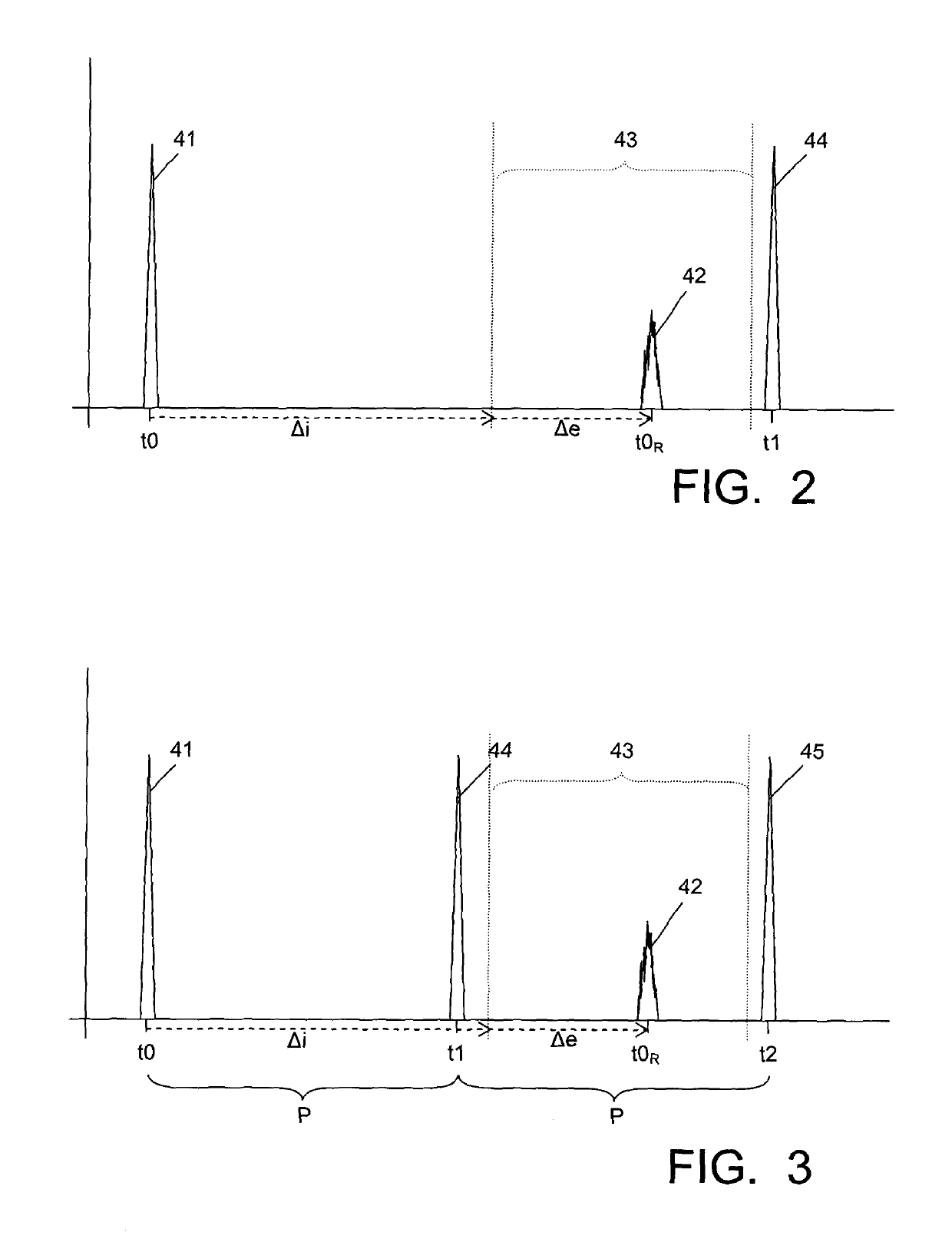
Another aspect of this complication is that the pulse measurement itself requires some measuring time, basically caused by the travelling time of the pulse from the ultrasonic transmitter to the reflection surface and back to the ultrasonic receiver.
If the inspection vehicles are too slow, they either disrupt regular service, or inspection can be done only during the night when traffic is reduced.
A drawback of this type of system is the relatively large consumption of coupling liquid.

Method used


Image

  • Mobile ultrasonic rail inspection system and method
  • Mobile ultrasonic rail inspection system and method
  • Mobile ultrasonic rail inspection system and method

Examples


Embodiment Construction

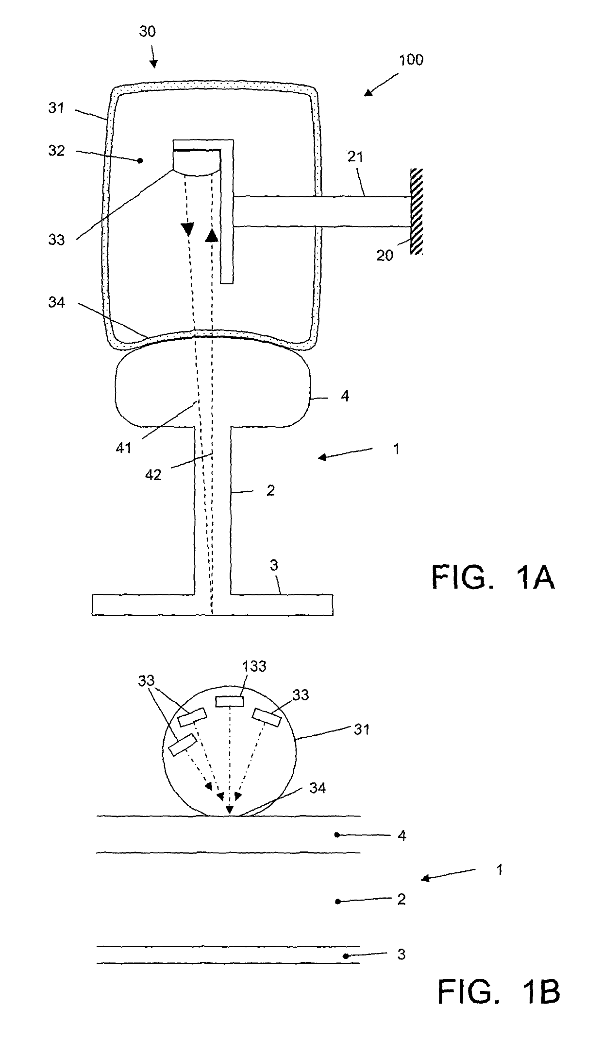
[0017]FIG. 1A schematically shows a cross-section of a rail 1, having a central rail body or web 2, a rail foot 3 and a rail head 4. A rail inspection vehicle 100 comprises a yoke 21 mounted to a frame 20. The vehicle 100 comprises an ultrasonic rail examination system 30, which includes at least one ultrasonic transducer 33 mounted on the yoke 21 within a rotating rail riding container 31 filled with coupling liquid 32, typically water or glycol or a mixture thereof. The rail riding container 31 is pressed onto the rail head 4. The wall of the container 31 is flexible, at least to a certain extent, so that the container wall conforms to the top surface of the rail head 4. A contact area of the container wall is indicated at 34. With travel of the vehicle 100 over the rail 1, the rotating container 31 rolls over the rail and is therefore also indicated as “wheel”. For a more detailed description of an example of such wheel-type system, reference is made to U.S. Pat. No. 5,419,196 by...


PUM

PropertyMeasurementUnit
angleaaaaaaaaaa
anglesaaaaaaaaaa
anglesaaaaaaaaaa

Abstract

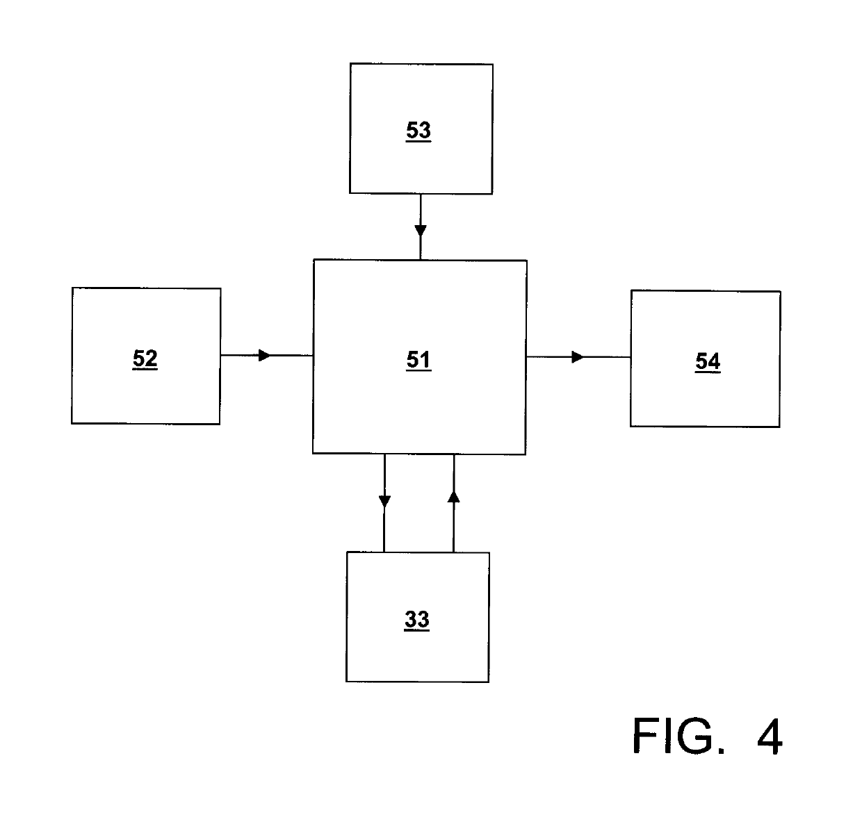
An ultrasonic rail inspection system includes an ultrasonic transducer mounted on a yoke for attachment to a frame of a rail inspection vehicle. The ultrasonic transducer transmits ultrasonic pulses and receives reflected ultrasonic pulses. A control device controls the ultrasonic transducer. A clock device provides clock signals to the control device. The control device controls the ultrasonic transducer to transmit the ultrasonic pulses at a fixed pulse repetition period.

Description

FIELD OF THE INVENTION[0001]The present invention relates in general to the art of detecting flaws, particularly cracks, in railroad rails.BACKGROUND OF THE INVENTION[0002]For safety reasons, it is important that railroad rails are inspected regularly for the presence of flaws or defects. A flaw or defect may be an existing small crack, or a location where a crack could arise. Cracks have the tendency to grow, and a broken rail may have catastropic consequences, so it is important to detect potential crack sites as early as possible. Many cracks are rarely visible from the outside; if they are, the rail is probably completely broken, and this is a situation that is to be avoided. Hence, a technology is required that is capable of detecting flaws in the rail.[0003]Such technology is ultrasonic measurement. Briefly said, an ultrasonic pulse is coupled into the rail, and the reflection of this pulse is captured. The pulse reflects from material surfaces, such as the outside rail surfac...

Claims


Application Information

Patent Timeline
Patent Type & Authority Patents(United States)
IPC IPC(8): G01N29/34G01N29/24G01N29/07G01N29/28
CPCG01N29/343G01N29/2493G01N29/28G01N29/07G01N2291/044G01N2291/0289G01N2291/011G01N2291/0234G01N2291/2623
Inventor BESTEBREURTJE, PIETER
Owner SONIMEX BV
Learn More